Wiring Up 2 Brush Dynamos
Wiring Up 2 Brush Dynamos
Rewiring a Lucas dynamo in it's original 'shunt' configuration seems to be straightforward at first glance. One of the potential pitfalls is trying to work out which is the 'start' and which is the 'finish' end of the field coil. Even if that can be worked out, it is still necessary to know whether the coil was wound clockwise or anticlockwise. Also, it is worth pointing out that just because Lucas wound the coil in one direction doesn't mean to say that the repro ones were done the same way....
No, it is easier to forget the theoretical ways in which it works and do it by trial and error as explained on this page.
Start by disconnecting everything in the dynamo.
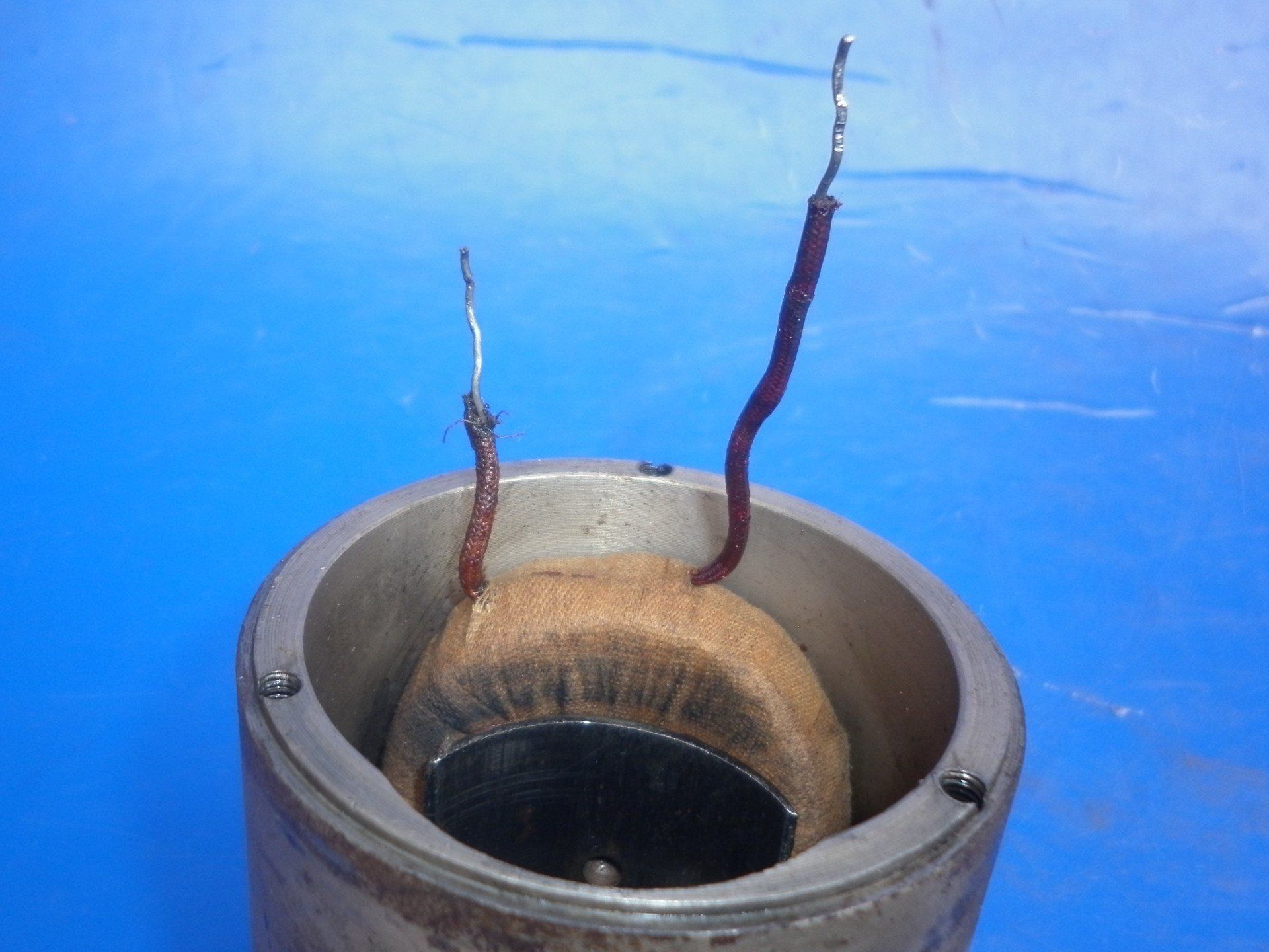
There will be two wires which disappear down into the 'innards' of the dynamo. These are the two ends of the field coil
There will also be a lead from each of the two carbon brushes.
So, four connections to be made in total - two brushes and two field coil connections.
Brushes
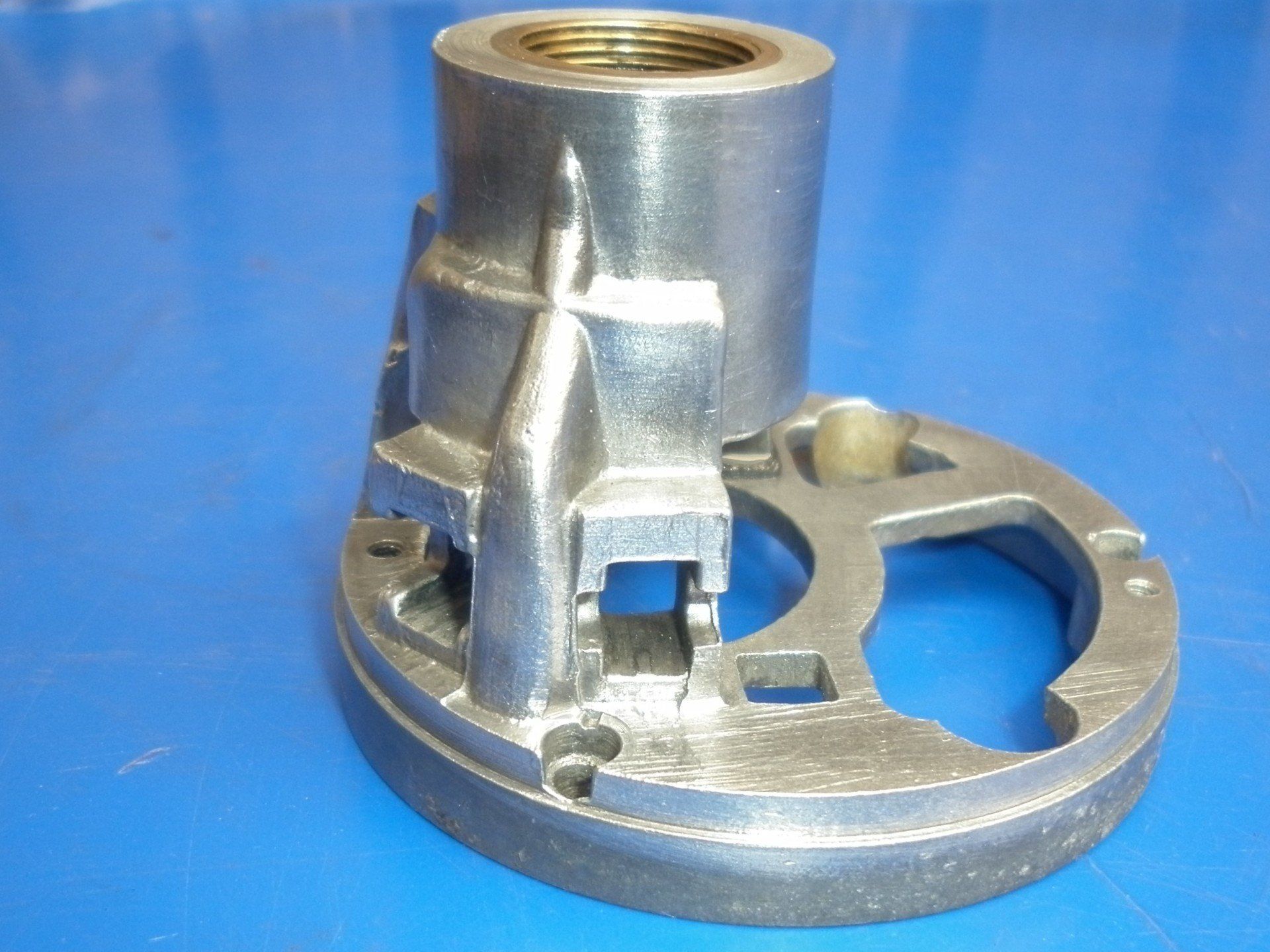
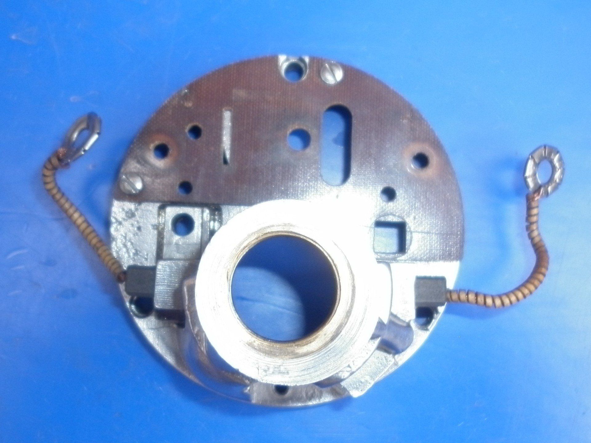
Have a look at the housings for the brushes. It was common in the early dynamos to have one brush housed direct in the aluminium body of the dynamo. In this case, there is not really any choice - that is the earth brush. On later dynamos, both brush holders are mounted on an insulating plate. In this case one is chosen to be the earth brush - usually the one which allows a neat, easy connection to earth.
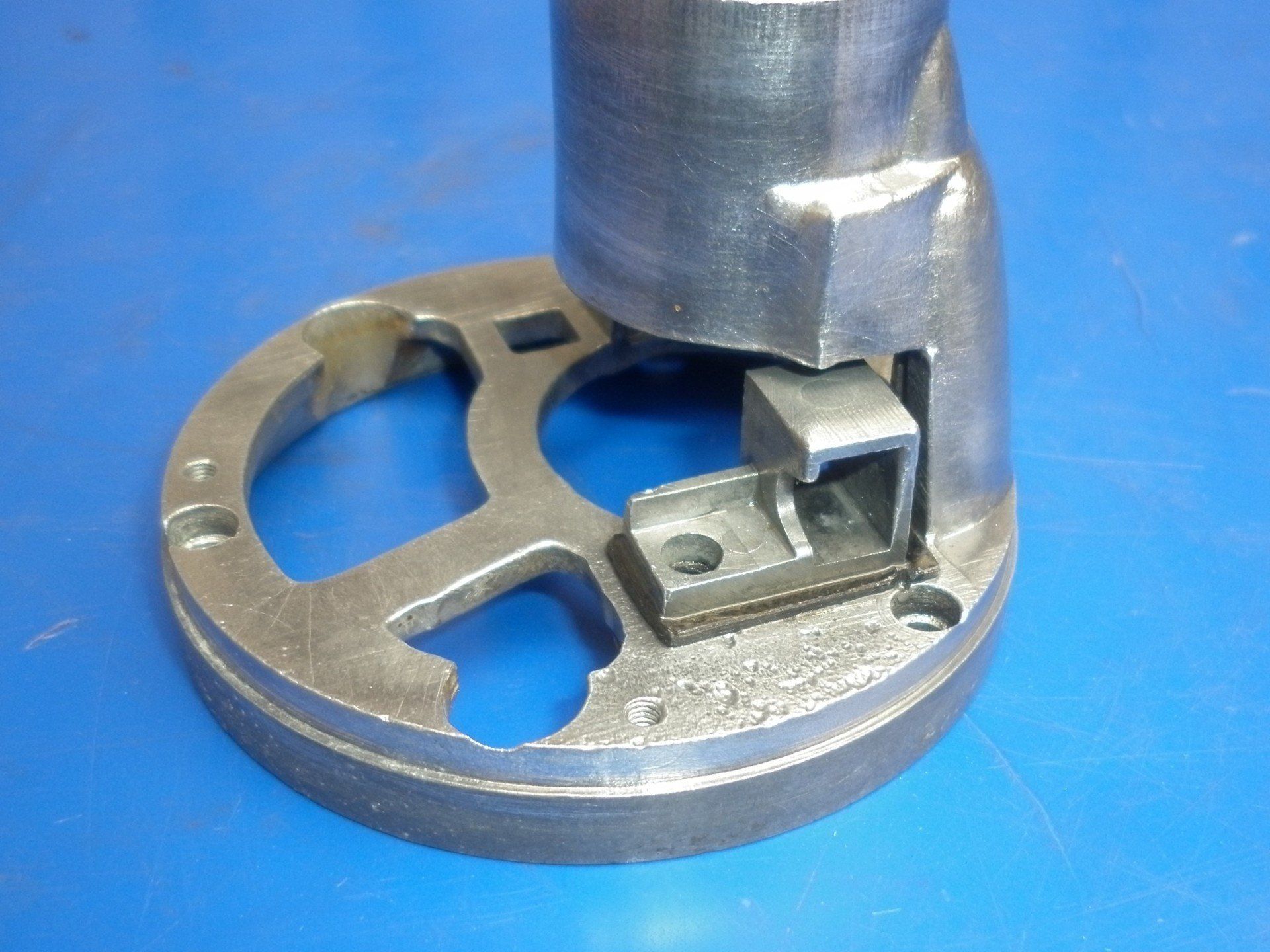
The remaining brush will always be mounted in an insulated holder similar to that shown here. This brush will be the dynamo output and will have a wire connection brought out of the dynamo and eventually off to the 'D' terminal on the voltage regulator.
Field coil
Choose one of the field coil wires as a connection to earth. The other wire will need to be brought out of the dynamo and eventually off to the 'F' terminal on the voltage regulator. It's best not make permanent connections to these wires just yet - it may be necessary to change them later. For the moment , make connections with test lead croc clips.
The dynamo now needs to be ‘motored’ as follows:
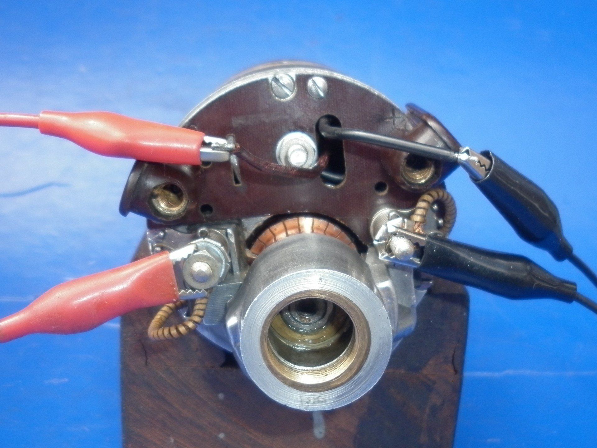
Clamp the dynamo in the vice so that it doesn't run away when it starts to turn.
Connect both the earth brush lead and chosen earth field coil wire to the 'earth' terminal on a battery (6v or 12v, it doesn't matter) - black test lead croc clips in the picture.
Connect both the 'D' brush and 'F' field coil wire together and then touch them on the 'non-earth' terminal of the battery - red test lead croc clips in the picture.
The dynamo should now 'motor'.
If the dynamo doesn't motor at all, it is faulty.
If the dynamo motors in the same direction as it will be turned by the engine when refitted to the engine, then everything is wired correctly.
If the dynamo motors but in the wrong direction, the two field coil wires need to be swapped over – the wire that was earthed now needs to become the 'F' terminal on the voltage regulator and the wire that was the 'F' terminal now needs to be connected to earth. Then connect to the battery as before. The dynamo should now motor in the correct direction.
Last test to carry out is to spin the dynamo and check that it is generating - details can be found here.
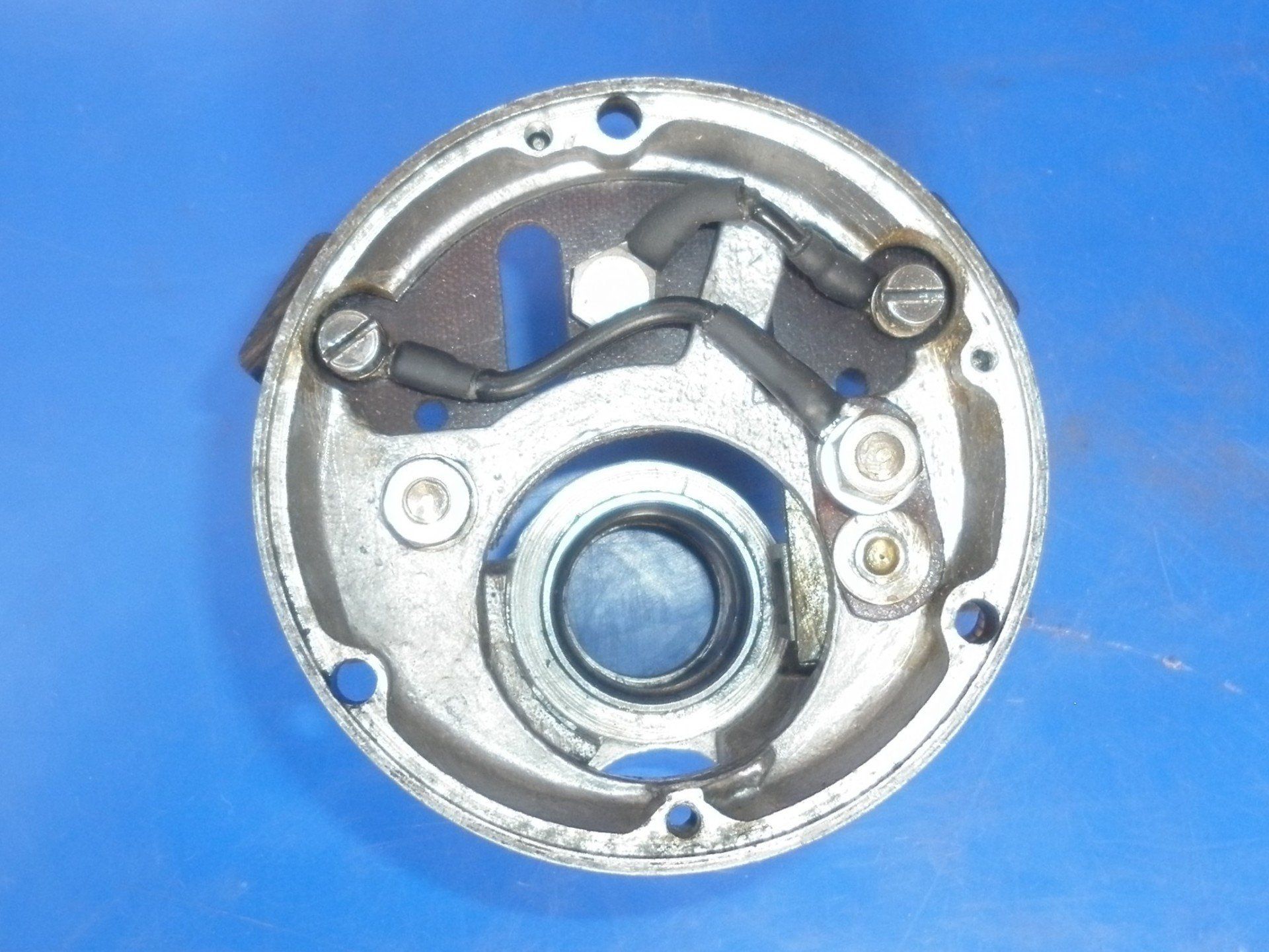
Once it has been determined which wire goes where and everything is working correctly, the connections can be made permanent. The Lucas E3H dynamo used in these pictures has two bakelite terminals for connecting the dynamo to the wiring loom. Wire links on the inside of the insulating plate are used to connect these terminals to the workings of the dynamo.
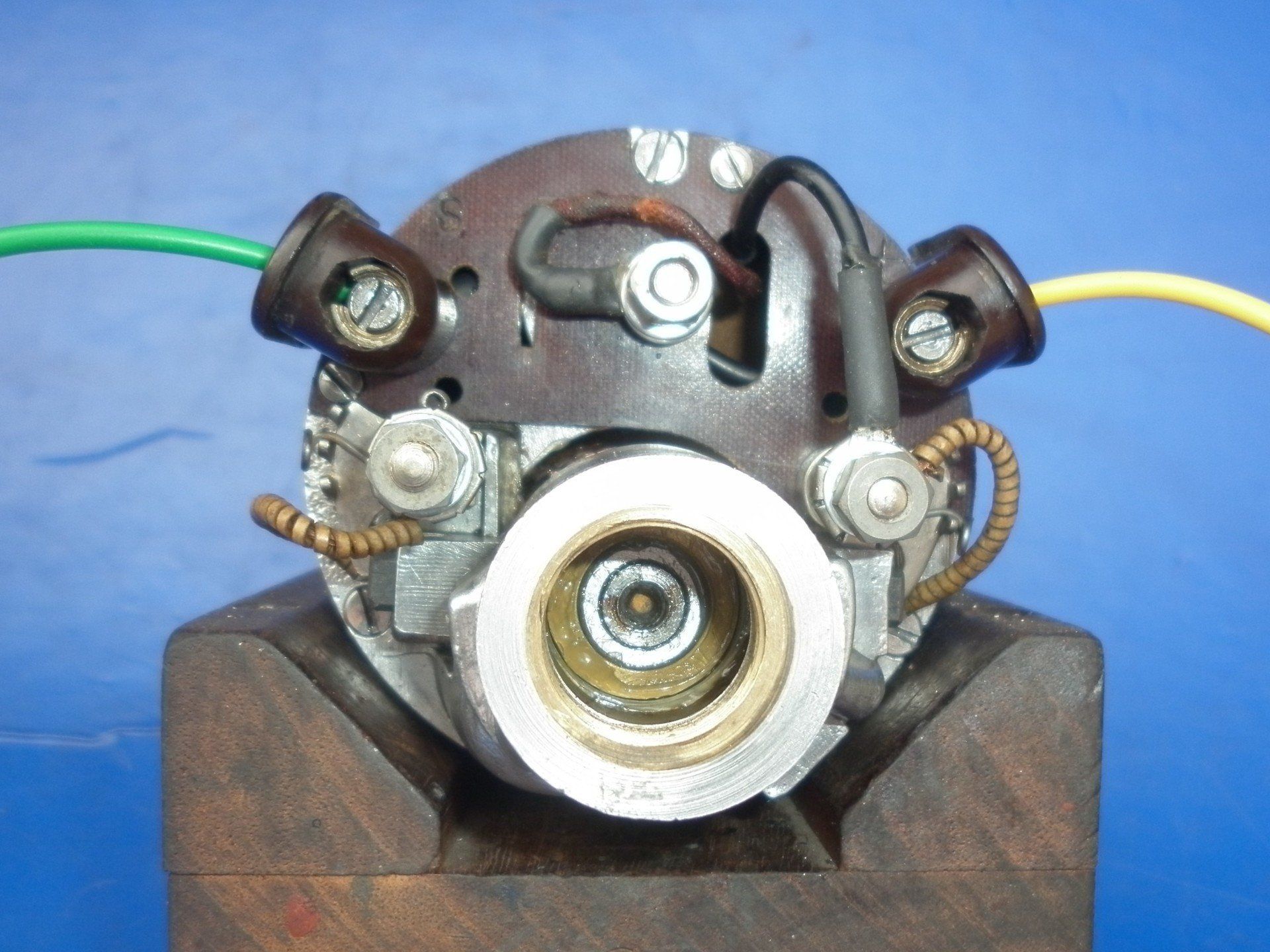
The dynamo can then be reassembled, the two field coil wires fitted with ring terminals and connections finalised. Here at The Magneto Guys, we always use a yellow wire for the 'D' connection and a green wire for the 'F' connections (think: green fields).
A few points to finish off with:
- Note the references to the 'earth' and 'non-earth' terminals on the battery. That's because the vehicle could be positive or negative earth - no matter, the same wiring and tests work for either. Actually, if the battery terminals are reversed and then the dynamo motored again, it will still go in the same direction. When the battery is connected as described for the motor test, there is one magnetic field caused by the current flowing in the field coil and a second, separate magnetic field caused by the current flowing in the armature windings. It's the interaction between these two magnetic fields that makes the armature turn and also determines which direction it turns in. If the battery terminals are swapped over, the current will be reversed in both the field coil and the armature windings but the relationship between the two will remain unchanged so the armature will still motor in the same direction. Remember that to reverse the direction, the field coil ends were swapped over which reversed the direction of current in the field coil only - the direction of current flow in the armature didn’t alter. Yes, the field coil could have been left alone and the brush terminals swapped over instead - that would reverse the direction too but is not usually quite so easily done especially if one of the brushes is mounted in an earthed housing.
- When experimenting with the wiring, always finish with a motor run with the battery connected to the dynamo as per earthing used on the vehicle. This will serve to 'polarise' the field coil the right way round. Just because it motors in the right direction does not mean it will charge correctly later on if it has been incorrectly polarised.........
- Note that these notes also show how to convert a three brush dynamo to two brush operation. The third brush and it's connections are simply not refitted!
- All this only works for a 'shunt' configuration which is what Lucas equipment had when it left the factory. Continental manufacturers (Bosch, Marelli and so on) used 'series' wound configuration so the above notes won't work for those. Be aware that just because your dynamo is a Lucas dynamo, it would be wrong to assume it's 'shunt' wound. Early electronic voltage regulators only worked with 'series' wound configuration so the internal wiring was changed accordingly...... More on dynamo configuration can be found here.
Regrettably, The Magneto Guys no longer work on dynamos - see our FAQs page for more details