Making a Twin Spark Magneto

Making a Twin Spark Magneto

The theory and general arrangement of a twin spark magneto is described in our Technical section here. Twin spark magnetos are not at all common and we are often asked if one can be made using a twin cylinder magneto as a starting point. This page explains one way of achieving this using a BTH Type KD2 twin cylinder magneto as a donor magneto.

First, a quick re-cap on what needs to be done:

This picture shows the normal connections in a conventional magneto. This arrangement is the method normally used on single, twin and multi cylinder magnetos. The primary winding, consisting of a few hundred turns of relatively thick wire, has it's start end connected to earth and the finish end connected to the points and condenser. The primary winding, points and condenser are all in parallel. The start of the secondary winding - several thousand turns of relatively fine wire - is normally connected to the end of the primary winding. The finish end of the secondary goes to the spark plug.
A two spark magneto has the same primary winding, points and condenser arrangement. However, the secondary winding on a two spark magneto is totally separate to the primary winding. Both the start and finish ends of the secondary winding are connected to one of two spark plugs. Both spark plugs are fitted in the same cylinder and both spark together.

For the primary winding on this twin spark magneto, a hole was drilled in the armature core. The start of the wire was passed through the hole and soldered in place. The rest of the primary winding and insulation was done in exactly the same way as on a conventional magneto as described here. On a two spark magneto the start of the secondary lies on top of the primary winding but it has to be insulated from it. When the coil is finished, the beginning of the secondary has to be brought out from the middle of the coil along the side of the steel core and insulated from that as well. The twin cylinder donor magneto used here is physically smaller than a genuine two spark magneto so great care and attention is needed to ensure that the secondary is extremely well insulated.
This picture shows the primary winding finished. It has then been wound with a layer of PTFE sheet, held in place with yellow polyester tape. On the left is a short length of 20g tinned copper wire in a PTFE sleeve. This is soldered to the start of the 46g wire used for the secondary winding - if the picture is enlarged, it can just be seen to the right of the yellow sleeved finish end of the primary coil. The soldered joint is sandwiched between two strips of PTFE which lay across the top of the primary winding and up the side of the armature core. Everything is held in place with more polyester tape. The secondary winding is then completed in the normal way.
The end of the secondary winding is completed in exactly the same way as with a conventional magneto resulting in one HT spout. The start of the secondary is then folded over the finished secondary winding and turned through ninety degrees to exit the winding along the centre line to produce the second HT spout. The path of this second HT spout is well insulated with PTFE sleeve over the wire and is also sandwiched between two PTFE sheets.

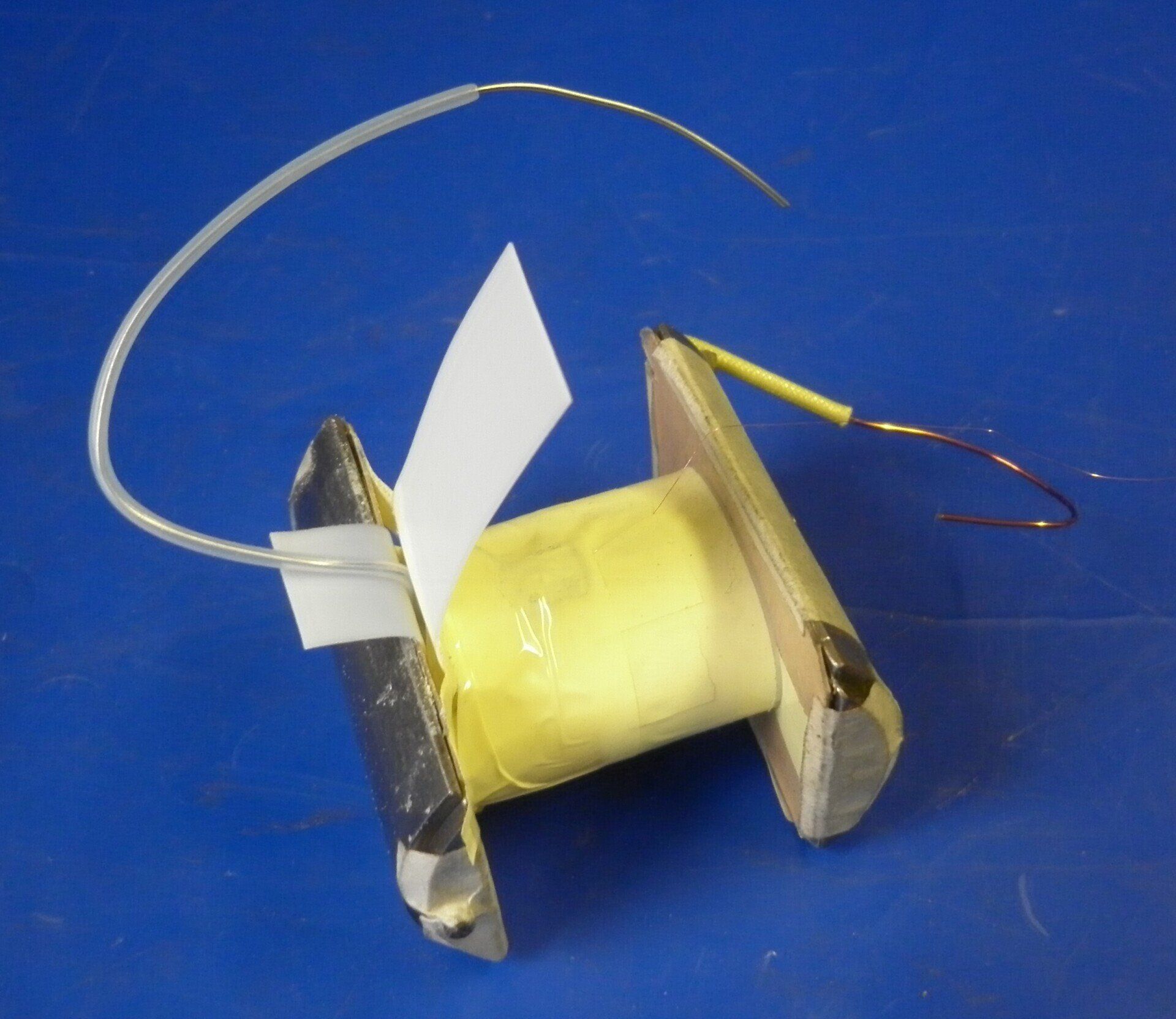
The picture shows the coil after it has been wrapped in Egyptian cotton tape and ready for the Vacuum/Pressure Impregnation  process.  The two wires in blue sleeves are the two ends of the secondary winding. On the far side,  the one with the dark grey sleeving showing past the end of the blue sleeve is the end of the winding. The other one, on the near side, with the grey sleeving showing past the end of the blue sleeve is the start of the winding. The wire in the yellow sleeve is the end of the primary - the start of the primary was soldered to the armature core. The primary and secondary windings are totally separate and well insulated from one another.


The drive end of the armature has an extra hole drilled to allow for the second HT spout. The other end of the armature houses the condenser and carries the points assembly exactly as with a conventional magneto.

The next job is to consider the slip ring requirements. This is obviously a completely non-standard part so needs to be made from scratch.

The component parts of the new slip ring are a fairly straight forward machining job. The four segment centre ring contains the two brass segments which will transfer HT voltage from the HT spouts on the coil to the carbon brushes in the pickups on the twin cylinder magneto body. The black parts are all machined from acetal rod.
The four segments of the centre ring are held together with a cable tie. The two acetal rings are placed on each side of the assembly and then the two side cheeks are slid into place. The HT spouts on the side cheek obviously have to line up with the brass segments. 
Everything should stay in place once all slotted together but the whole assembly can be assembled with araldite as an extra safety measure. It is then held together with a clamp until it has set. The assembly is then mounted on a stub arbor in the lathe and the centre ring machined to provide a smooth path for the pick up brushes. A small hole is drilled through each of the two spouts into the brass segments to provide a connection for the two HT spouts on the coil.

The last change to make is the easiest - simply replace the original twin cylinder cam ring with one meant for a single cylinder! The magneto is then assembled in the normal manner and is ready for testing.


The 'new' twin spark magneto used here to illustrate the work involved was fitted to a racing Norton Manx motorcycle.


A few comments to finish off with:

If the two spark plugs are positioned in the best places in the cylinder head, the dual spark will produce a better, faster flame front. To get the best out of this, it may be necessary to alter the ignition timing compared to what is considered best for the same engine fitted with a single spark plug.

With a twin spark magneto, both spark plugs fire together. The HT passes from the magneto along one HT lead to the first spark plug, travels down the centre electrode and jumps the gap to the earth electrode. It then travels across the cylinder head and jumps the gap from the earth terminal on the second plug, travels up the centre electrode and along the second HT lead back to the magneto. So one plug will produce a positive spark, the other produces a negative spark. More info on Spark Polarity is covered here

One of the factors affecting the size of the HT voltage needed to jump a spark gap is the size of that gap. Other factors affecting Voltage at the Spark Plug are covered here. Obviously, the higher the voltage the better the insulation needs to be. For this reason the spark plug gaps are often reduced to 0.015" when using twin spark magnetos.

It is extremely important that all connections in the HT path are tight and in good condition. HT voltage will take the path of least resistance to ground so a poor connection may result in a short to earth in the magneto coil. For the same reason, it is also extremely important that a spark plug lead does not jump off the spark plug!

As with any magneto, it is important that a twin spark magneto is not spun without both the spark plug terminals being grounded or connected together.
Share by: