Dynamo Cut Outs
Dynamo Cut Outs
Electrical current in a completed circuit will flow whenever there is a potential (voltage) difference between two points in the circuit. The current always flows from the higher voltage to the lower voltage. So, for instance, when a bulb is connected across a battery, current will flow from the battery positive terminal through the bulb to the battery negative terminal lighting up the bulb in the process. This basic theory becomes a little more involved when there is more than one voltage source such as when a dynamo is added to the circuit.
When the engine is started and the dynamo starts to spin, it will produce an output voltage which will be proportional to it's rotational speed. As the speed increases, so does the output voltage until it eventually reaches a value greater than the battery voltage. As already stated above, current will flow from the higher voltage (the dynamo) to the lower voltage (battery) - current will flow from the dynamo into the battery thereby charging the battery.
Of course, when the engine and dynamo are stationary, the dynamo will obviously not be generating any voltage and the voltage at the dynamo output terminal will be at zero volts. This is obviously less than the battery voltage so now current will flow from the battery into the dynamo.
So current can flow in both directions in the wire between the dynamo and battery. The direction of the current flowing in that wire is easily indicated by breaking the wire and joining the two ends to the terminals on an ammeter. The ammeter will then display the current direction as either 'Charge' (current flowing from dynamo to battery) or 'Discharge' (current flowing from battery to dynamo).
In practice of course, it is not desirable to have current flowing from the battery into the dynamo as the dynamo will act as a load on the battery and, if left alone, will fairly quickly flatten the battery. To prevent this, a cut out is added which acts as a kind of 'one way' valve so that current is free to pass from dynamo to battery but is prevented from flowing from battery to dynamo.
Some early dynamos used mechanically operated cut outs. This first example shows a Splitdorf DU1 dynamo. The system consists of a doughnut shaped ring fitted to the end of the armature and pivoted along a diametric line indicated by the slotted screw.
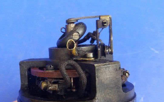
This picture shows the dynamo at rest. When the armature starts to spin, the doughnut ring will be subjected to centrifugal force which will cause the ring to flatten out. When it does this it will operate on the linkage connected to the contact points shown on the right resulting in the contacts closing. The output from the dynamo is then connected to the output terminal and off to the battery. When the dynamo stops, the doughnut ring falls to one side, the contacts open and the dynamo/battery connection is broken.
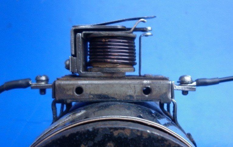
A more common design is an electro-mechanical system as shown in this picture - basically a relay. The dynamo output voltage is used to energise the relay coil. When the dynamo spins fast enough to generate a high enough voltage to operate the relay, the contact points close and connect the dynamo output to the battery. When the dynamo slows down, the voltage generated will drop, the relay contacts open and the dynamo/battery connection is broken.
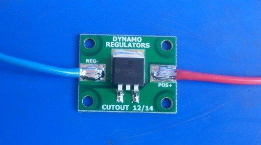
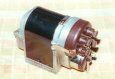
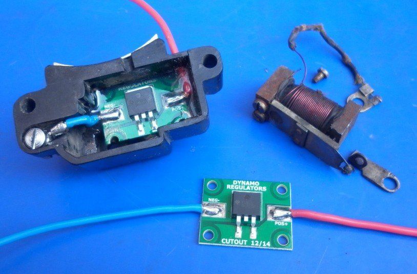
There is a third type of cutout which, although not original, has proven to be a very reliable and effective alternative - modern day electronics! Here at The Magneto Guys, we often fit this Smart Cut Out from Dynamo Regulators Ltd.
in place of the original cut out.
Unfortunately Dynamo Regulators Ltd have now discontinued this product so The Magneto Guys have decided to produce their own Smart Diode Cut Out - available now - click on the link for full details.
The circuit board used for the Smart Cut Out can usually be trimmed to enable the unit to be fitted into an original enclosure. This picture shows a Smart Cut Out fitted to a Maglita replacing the original electro-mechanical cut out. Maglitas
incorporate a two brush dynamo but differs slightly from the usual two brush dynamos in that the magnetic field is supplied by a pair of permanent magnets so is at a fixed strength.
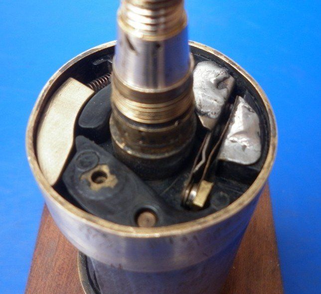
Other versions of the Maglita incorporated a centrifugal switch in the end of the armature as shown in this picture. A weight flings out and closes the contacts when the speed goes up and a spring on the weight opens them again when the speed slows down. Our experience of these switches shows that the cut in and cut out speeds vary considerably not only from one armature to another but also for successive operations on the same armature! Here at The Magneto Guys, we bypass the mechanical switch by soldering the contacts together.........
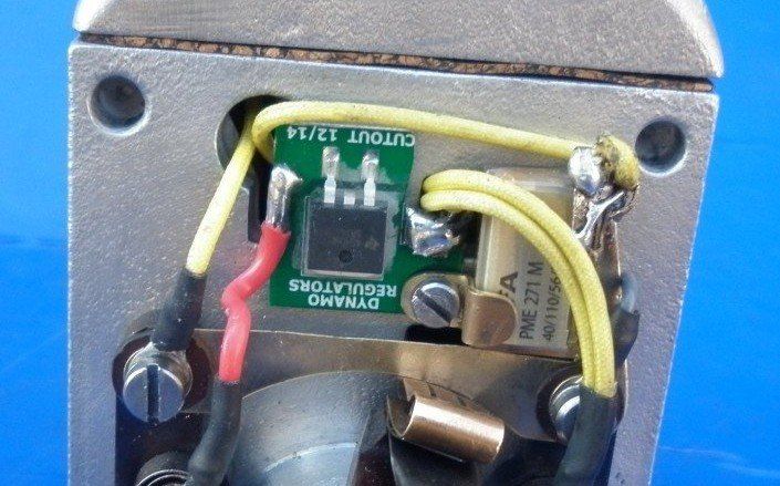
........... and then fitting a Smart Diode Cut Out. It can be seen that the printed circuit board has been trimmed to allow it to fit in the available space.
This picture also shows the EVOX RIFA PME271M capacitor which we fit in place of the original condenser - more details here.
All dynamos, both two and three brush versions, have to be fitted with some kind of cut out to prevent the battery discharging through the dynamo armature when left standing. Three brush dynamos are self regulating as far as output voltage is concerned as described here
but they still require a cut out similar to one of the types shown on this page. Two brush dynamos use a regulator
to change the amount of current flowing through the field coil. This controls the strength of the magnetic field around the field coil which in turn controls the dynamo output. They also require a cut out for the same reasons and this is usually (though not always) incorporated in the regulator unit which should probably be more accurately referred to as a regulator/cut out.
Regrettably, The Magneto Guys no longer work on dynamos - see our FAQs page for more details