Dual Magnetos-Single Plugs

Dual Magnetos - Single Plugs

There are two basic types of ignition system commonly used on veteran, vintage and classic engines – the magneto and the battery/coil. Particularly in the early years, battery technology was not at all reliable and it was rare to find a manufacturer relying solely on a battery/coil ignition system. Eventually, battery technology (and charging systems) had improved to the point where they became the most common type of ignition system and magnetos gradually fell out of favour. Magnetos were comparatively expensive to manufacture and eventually disappeared except for a few specialist applications. Nowadays, magnetos are still found on many small engines used to power garden/farm  machinery and generators. They are also to be found on competition vehicles and piston engined aircraft. Each system has it’s good points and it’s weak points.

A magneto is a complete self contained system. It needs to be turning to generate sparks and it produces a weak spark at low kickstart/cranking speeds. Once the engine has started however, a magneto's spark improves as the speed of rotation increases.

A battery/coil ignition system produces a very good spark at low starting speeds - in fact the engine does not need to be turning at all as a spark can be created simply by opening the contact breaker points. The down side of this system is that it requires a good battery and probably a good charging system although some applications such as racing/competition engines use a  total loss system - the battery is chosen as one capable of supplying enough power to last the race. An external charger is then used to recharge the battery between races.
By the early 1900s, most of the major magneto manufacturers had put together their own versions of an ignition system which used the best parts of both systems, known as a Dual Ignition System.

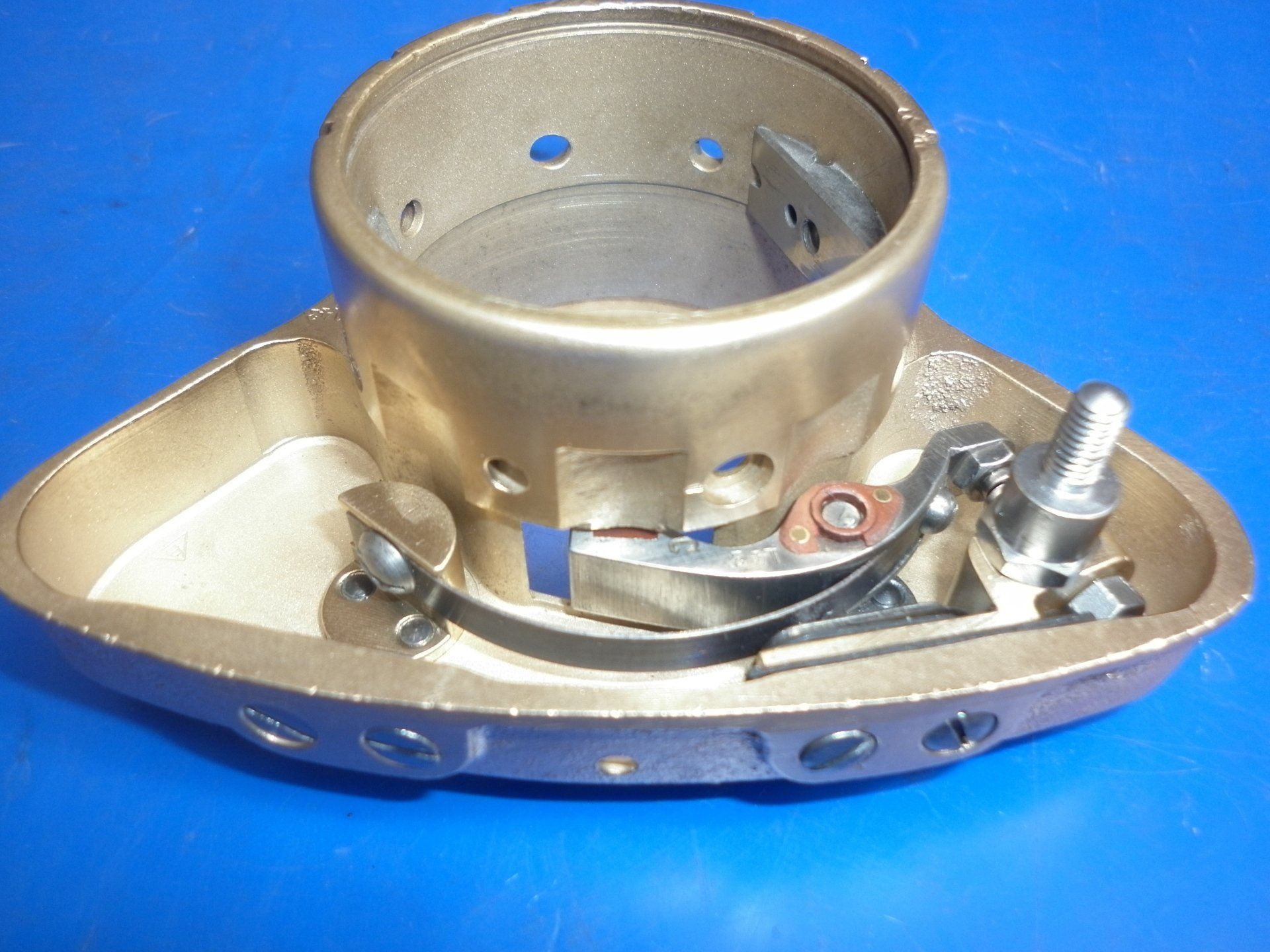
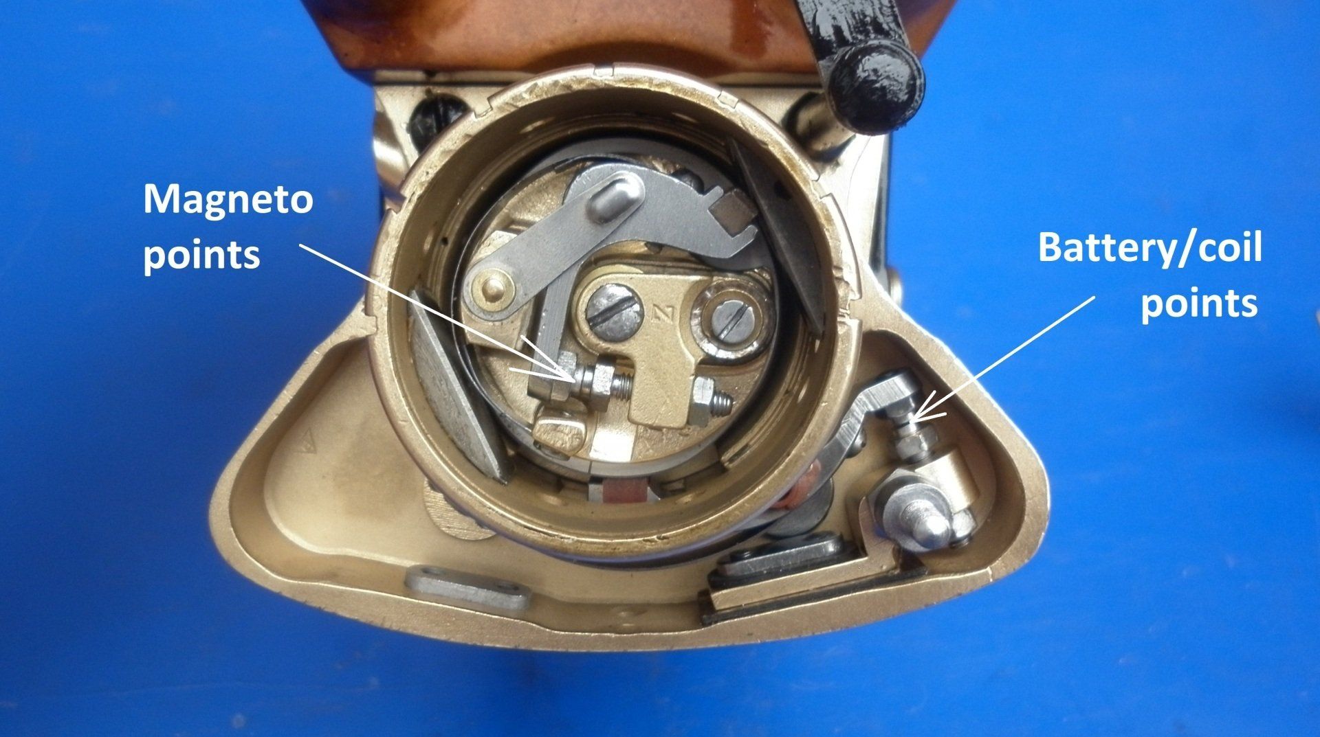
A dual magneto is basically a standard magneto system with the addition of some extra parts including a second set of contact breaker points and a cam which are used by the battery/coil section.

One set of contact breaker points is mounted on the armature and rotates with it. These points are opened by a pair of stationary cams and are used by the magneto section - A in the picture.

On the back of this points assembly is mounted a rotating cam - B in the picture. This cam opens the second set of contact breaker points which are stationary. These parts are used by the battery/coil section.

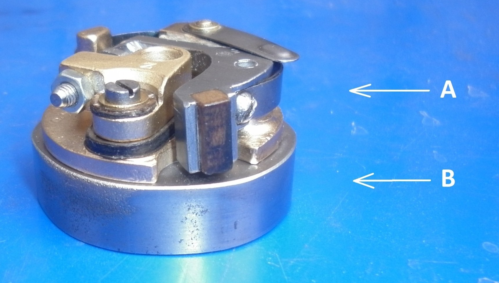
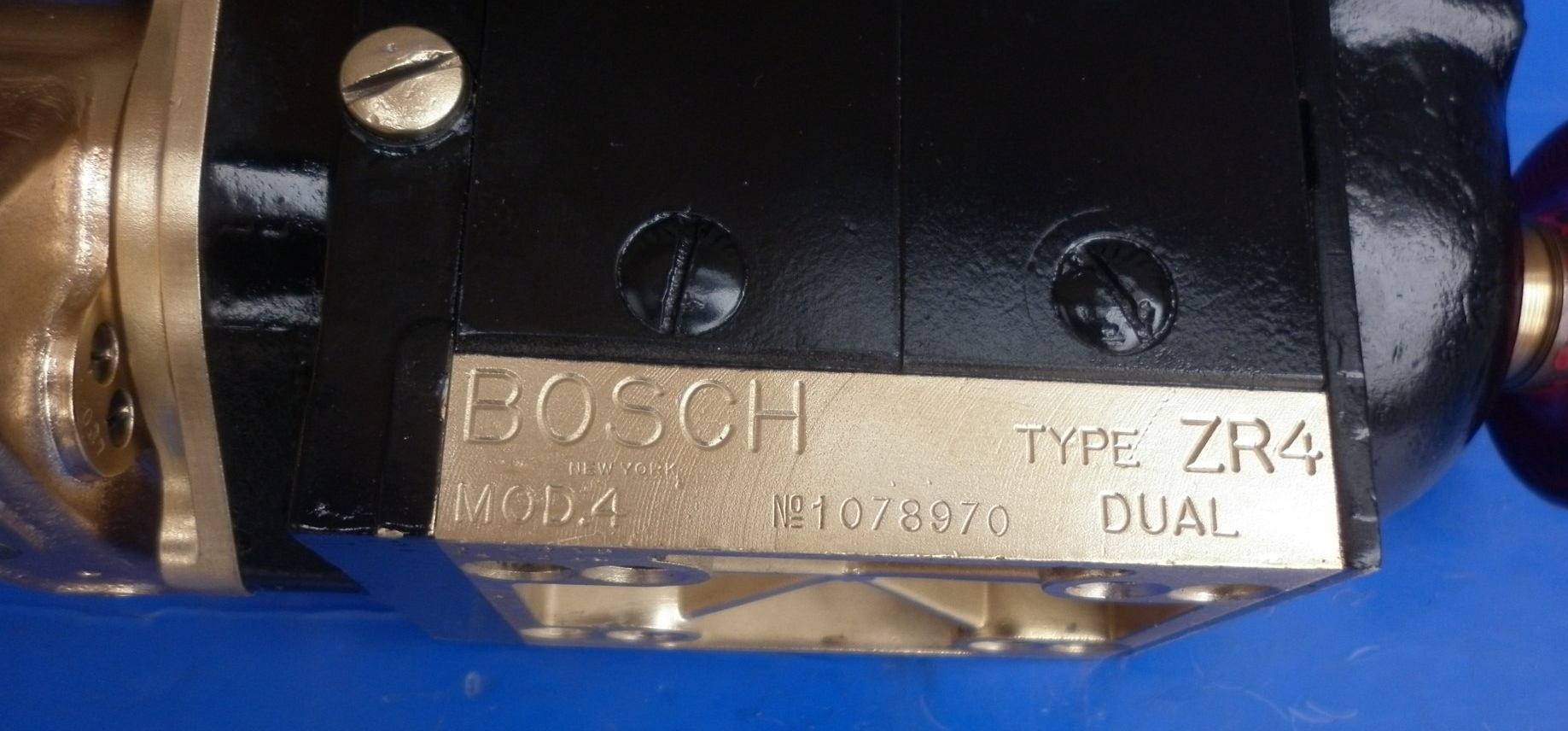
Note that the battery/coil points are fitted on one side or the other depending on the direction of rotation of the magneto. The threaded stud is for connecting a low tension wire which runs to the battery powered HT coil.


The battery/coil system requires it’s own HT coil and, of course, the battery. These are external components and are not part of the dual magneto itself. The only shared components used by both the magneto and battery/coil systems are the rotor arm and distributor mounted on the magneto and, of course, the HT leads, caps and spark plugs. To complete the system, a special changeover switch is mounted on the dashboard. The driver can switch to battery/coil ignition to start the engine and then, once the engine is running, switch to the magneto for normal driving. The design of this changeover switch is quite complex. It is actually a multipole switch. As well as switching the HT consisting of thousands of volts, it also has a number of low tension circuits to select the source of the HT.
When the switch is set to battery/coil (for starting):
1: the HT coil output is connected to the rotor arm/distributor
2: the battery is connected to the HT coil
3: the magneto primary winding is shorted to ground to disable the magneto section
When the switch is set to the central 'off' position
1: both the magneto HT and the HT coil output are disconnected from the rotor arm/distributor
2: the magneto primary winding is shorted to ground to disable the magneto section
3: the battery is disconnected from the HT coil to disable the battery/coil section 
When the switch is set to magneto (for normal running):
1: the magneto HT is connected to the rotor arm/distributor
2: the magneto cut out is opened
3: the battery is disconnected from the HT coil to disable the battery/coil section 

The three position switch as supplied by Bosch is labelled 'M' for magneto, 'O' for off and 'A' for accumulator  (early name for battery). It was never intended for these versions of dual magnetos to supply both magneto and battery/coil ignition at the same time. Early on, the HT coil used by the battery/coil system was mounted on the bulkhead/fire wall but was then incorporated in the change over switch.

The points used by the battery/coil section are timed to give a retarded spark compared to the points used by the magneto section. This ensures that the engine is much less likely to kick back when being started.

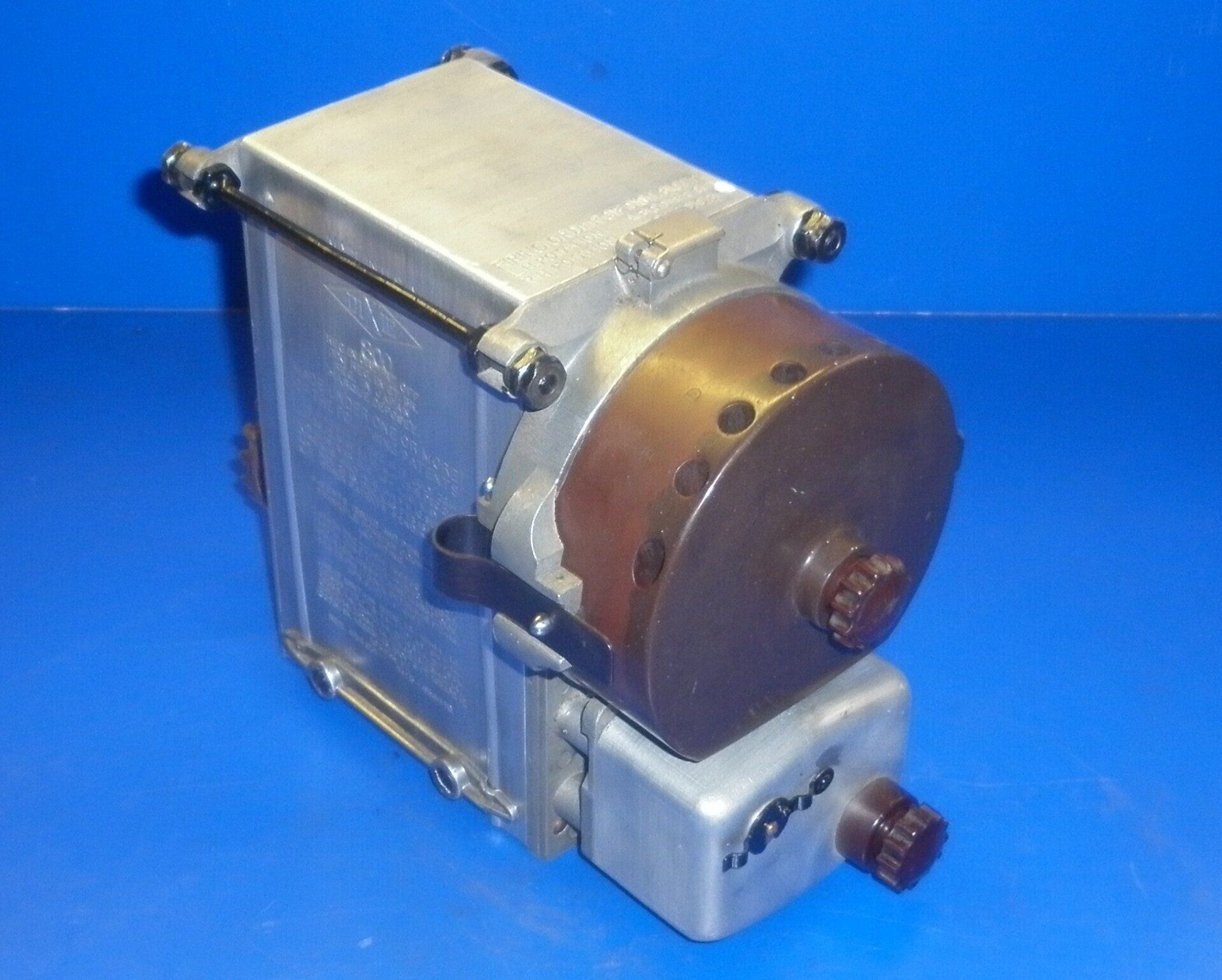
The way in which one or other of the HT sources is fed to the spark plugs is most commonly achieved by incorporating an extra terminal on the magneto's distributor cap. A  carbon brush connects this terminal to the rotor arm. This picture clearly shows this terminal on a Dixie 800 magneto. Other manufacturers including Bosch, Eisemann, Simms and SEV amongst others used this method.

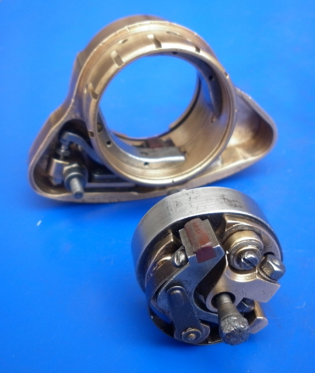
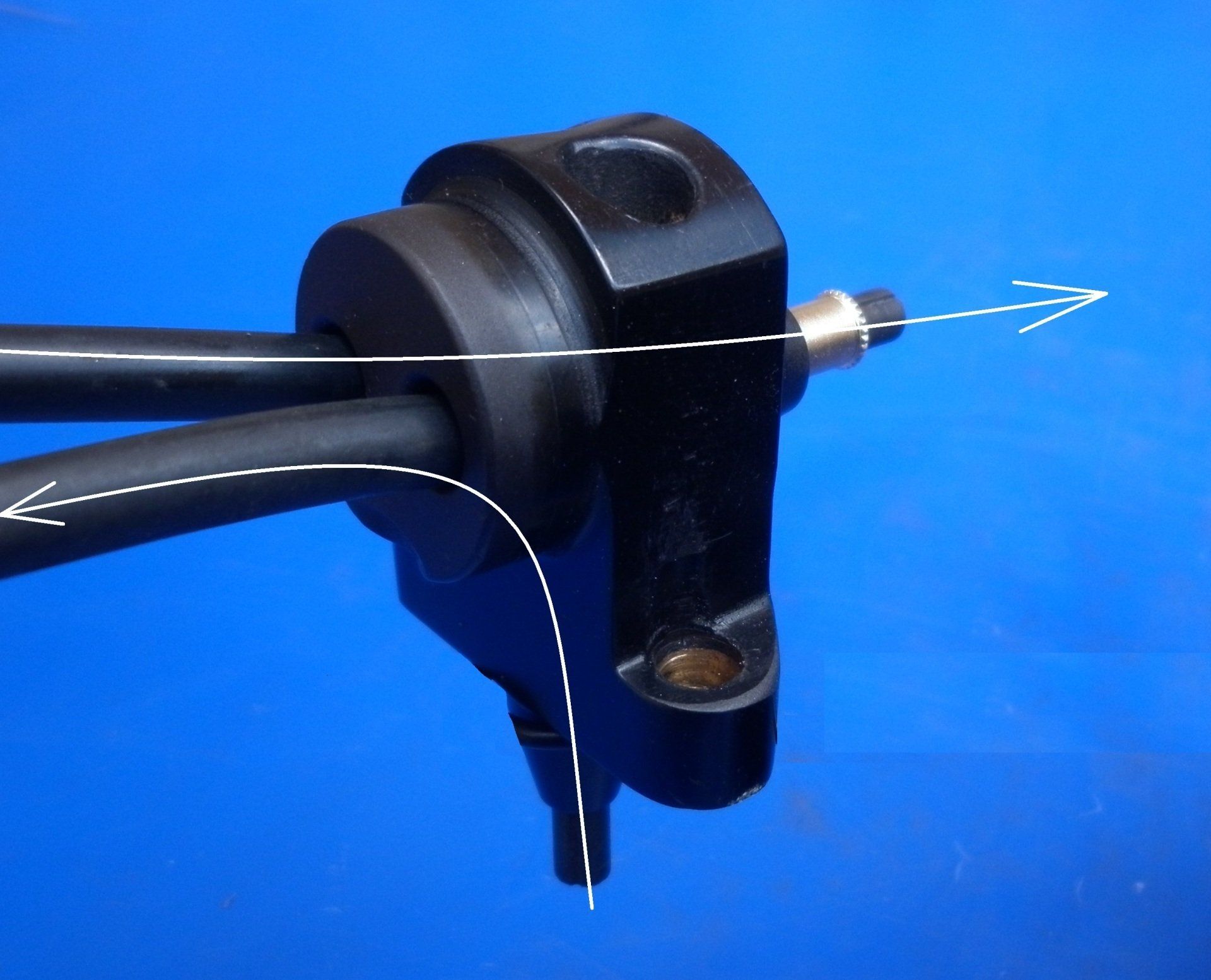
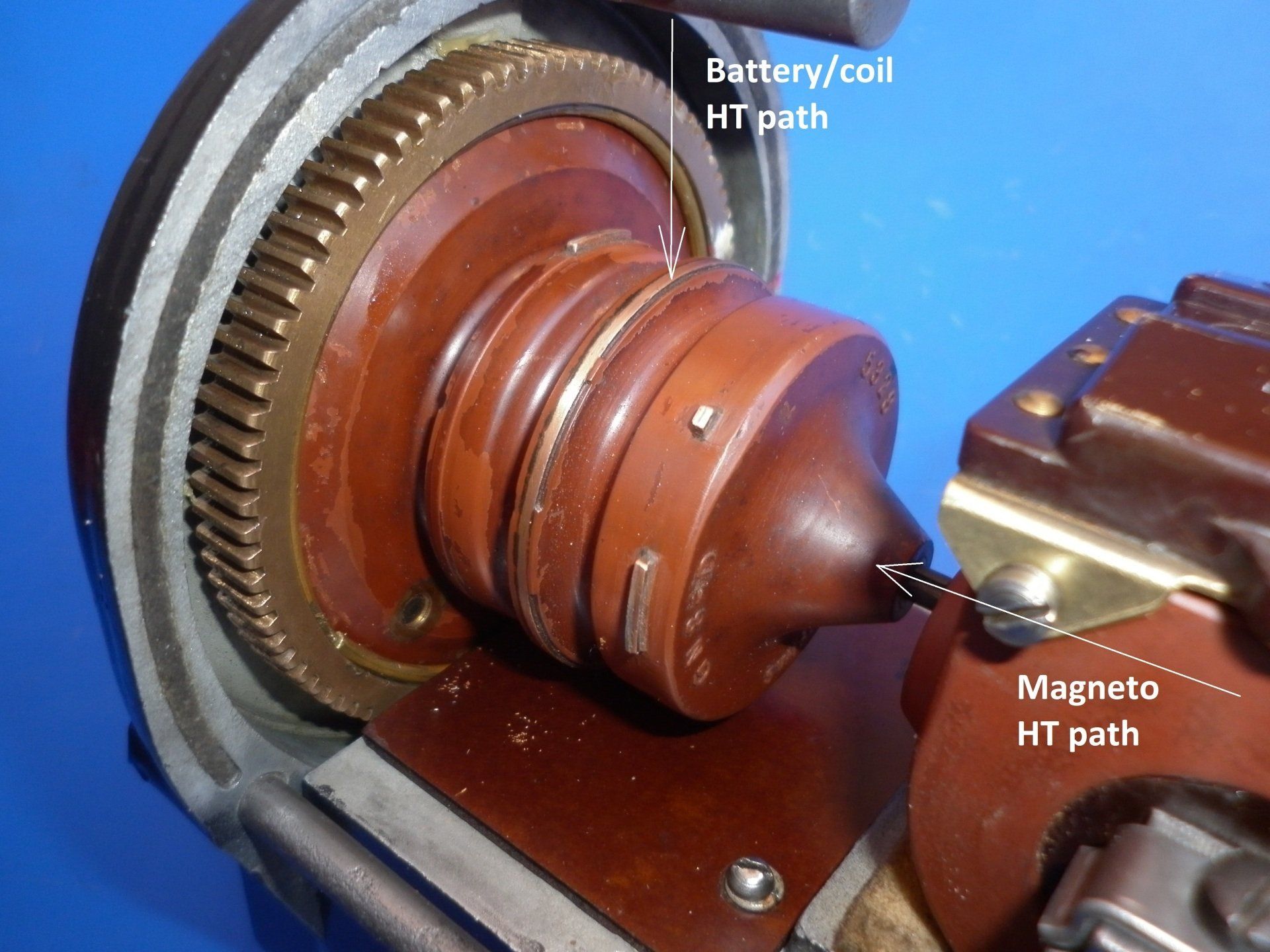
On some dual magnetos including those from BLIC and the Bosch ZR series, a special pickup is used which has two independent paths. One takes the magneto HT out of the magneto on it’s way to the changeover switch. The other path takes the selected HT from the switch into the magneto, under the arch of the magnet itself to the rotor arm and distributor and then on to the HT leads and spark plugs. This method allowed the dual magnetos to use the same rotor arm and distributor cap as the standard range of magnetos.

On this Scintilla GN8-D magneto, the battery/coil HT input is via the black lead into the top of the distributor cap.

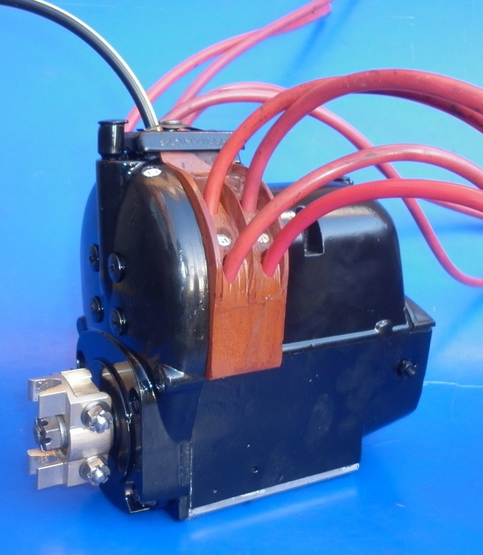
A spark gap connection is made to the continuous brass ring in the centre of the rotor arm. This is linked to the carbon brush connection from the magneto HT. The rotor arm then distributes the HT via spark gaps to each of the red HT leads and then to the plugs.


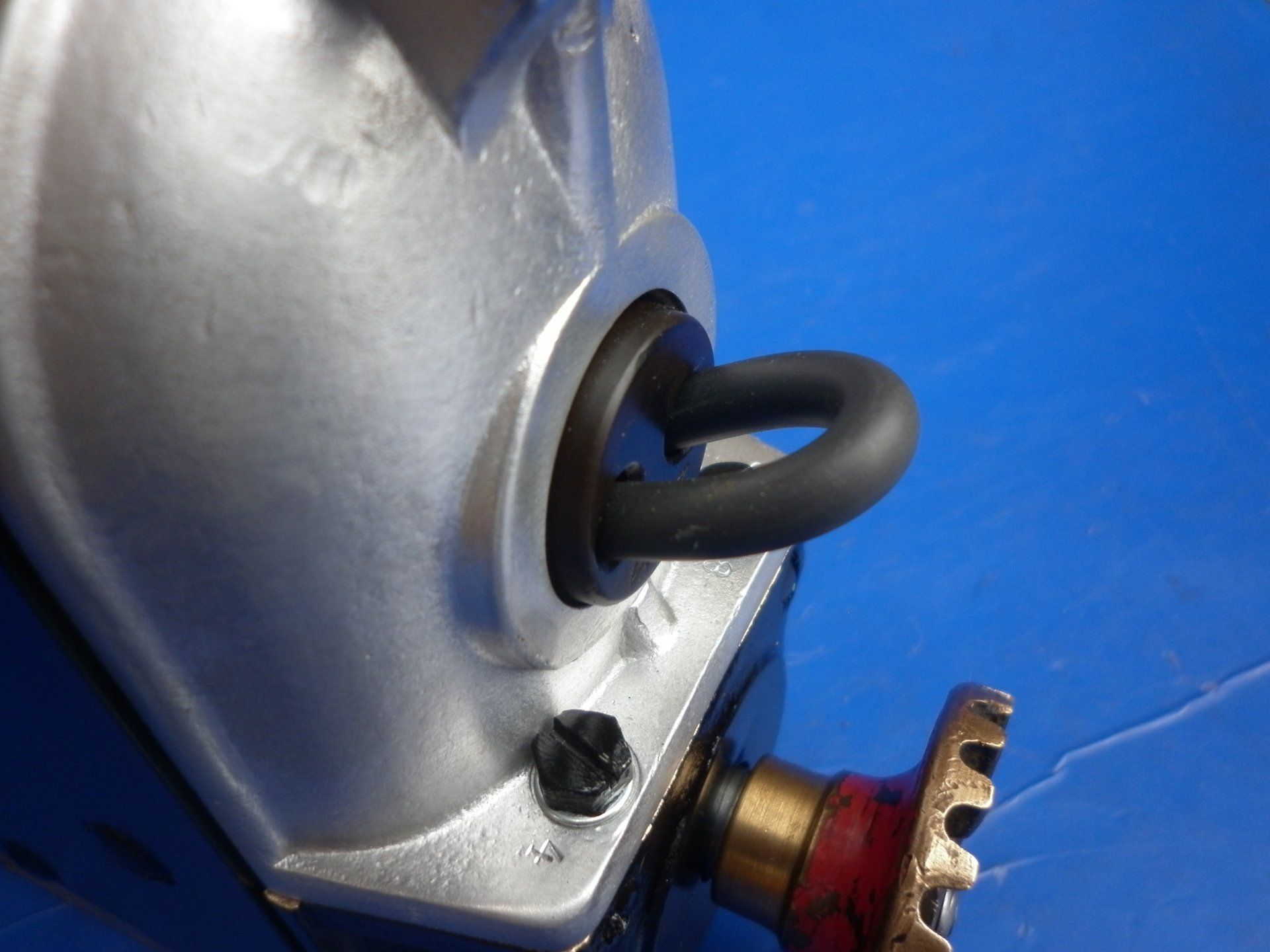
It is not uncommon to find that a dual magneto is fitted on it’s own with no battery/coil system and no changeover switch. This is easily achieved by simply having a small loop of HT cable fitted between the HT output and input. The second set of points is usually left in place but is not used at all.


Magnetos used for early aircraft engines have some similarities with the dual magnetos described on this page. However, instead of using a battery/coil system as an alternative to the main magneto, they use a second independent magneto to assist starting. They are known as Aircraft Starting Magnetos .


The dual magnetos described here allow the driver to provide one set of spark plugs with HT supplied by either a magneto or battery/coil system. This is often described as a dual magneto for a single set of spark plugs (one per cylinder). Another variation is Dual Magnetos for a Twin Set of Spark Plugs (two per cylinder) .

Share by: