Three Brush Dynamos
The main advantage of the three brush design is it's simplicity and ease of maintenance. The main disadvantage is that a three brush dynamo will only charge at a fixed rate – not ideal when the electrical load varies due to, for instance, driving/riding with or without lights. This is a major drawback and although various attempts were made to address it, the three brush design was eventually superseded by the far more efficient two brush design. Three brush dynamos are easily converted to work as a two brush system and is something we normally recommend. Details of how to do this are given on the Wiring Up 2 Brush Dynamos
page. However, for some owners, originality is more important so for those, the following notes may be of interest.
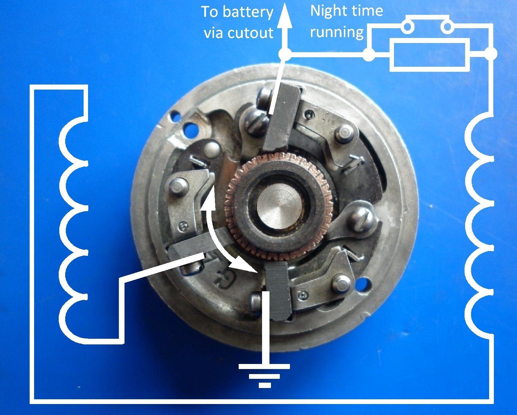
A three brush dynamo is simply a normal shunt configuration
fitted with an extra control, or field, brush - usually thinner than the other two brushes. The two main brushes look after the charging current, and the third brush is placed in such a position on the commutator that it picks up only part of the generated voltage which is then fed to the dynamo field coils. The following picture shows one of a couple of ways in which these component parts are wired up inside the dynamo:
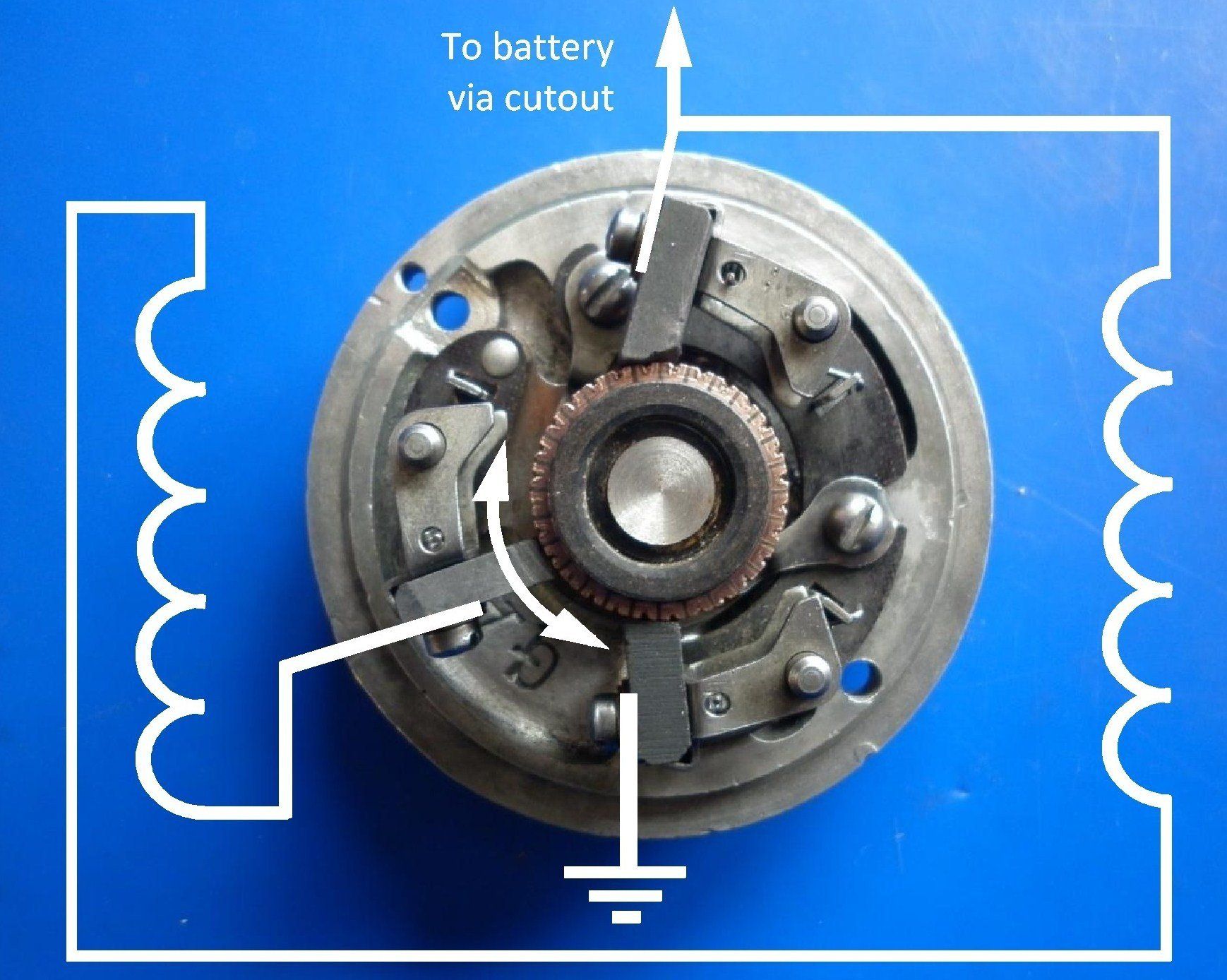
This method of generation, known as the armature reaction type, relies on the interaction between the magnetic field produced by the flow of current in the armature coils and the main magnetic field of the dynamo created by the current flowing in the field coils. As the armature speed increases, there is a distortion of the magnetic flux produced by the field coils, such that the field brush picks up less current to supply the field coils. This means that the armature rotates through a weaker magnetic field thus reducing its output proportionately. The charge rate therefore remains approximately the same over all engine speeds. It may even drop slightly at high engine speeds owing to the larger flux distortion.
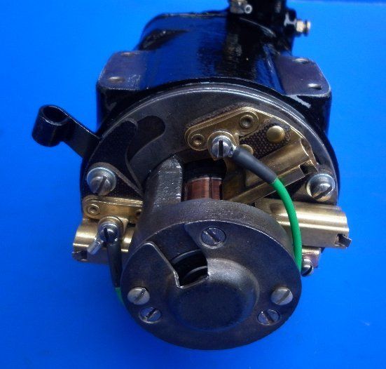
Some three brush dynamos have the third brush mounted in a fixed position (12 o'clock on this example) almost mid way between the two main brushes (9 and 3 o'clock). With this design, the charging rate is fixed by the manufacturer and there is no means of adjustment within the dynamo itself.
A more common design, shown in the first picture above, allows the position of the third brush relative to the main brushes on the dynamo to be adjusted. Initially fixed at time of manufacture, it can subsequently be changed at servicing or overhaul time if required after which it remains fixed until the next service. By moving the position of the field brush, the voltage applied to the field coil can be varied, with consequent increase or decrease of charge rates. To increase the charge rate, move the field brush in the same direction as the rotation of the armature. To decrease, move the brush against the direction of rotation. This is an improvement on the previous design but, once adjusted, still gives only one fixed charging rate.
Controlling the charge rate
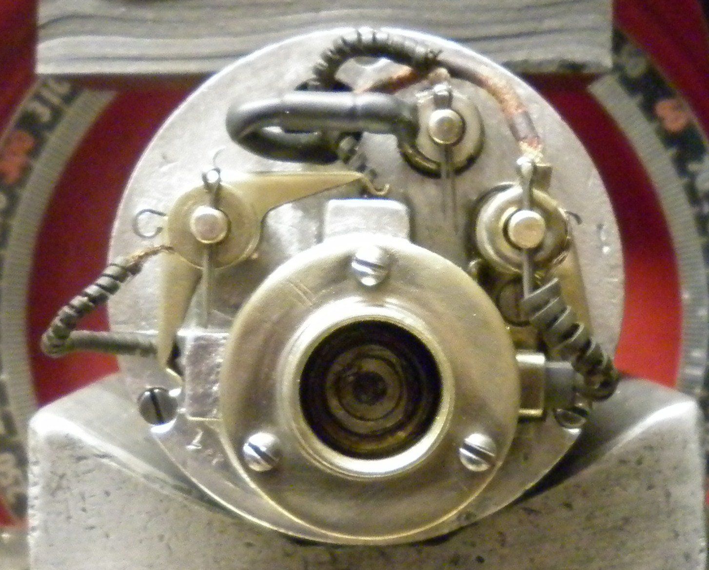
In an attempt to address the problem of a single fixed charging rate, some three brush dynamos have an external lever which allows the third brush to be adjusted at the will of the driver/rider. Use of the vehicle’s ammeter can be used to ensure that the charge rate matches the electrical load. One such example is the Harley Davidson Model D generator from 1929 shown here.
A more common way of achieving the same result is to switch in a resistor in series with the field coil. This reduces the current flowing in the field coil thereby reducing the charge rate. When the resistor is shorted out, the field coil receives the maximum current which gives maximum charge rate. This resistor is often switched in and out of circuit by the same switch that operates the lights so in some respects can be considered to be ‘automatic’ adjustment.
Resistor shorted out - maximum charge rate

Resistor in circuit - minimum charge rate
Sometimes, more than one resistor is used so that a number of charge rates are available. Some vehicles have a ‘winter/summer’ or a ‘half charge/full charge’ switch setting to control the field current in the same way. Despite these improvements, because three brush dynamos provide current regulation only and do not take battery voltage into consideration, it is still likely that the available charge rate options will not match the immediate needs of the battery.
WARNING
- When making adjustments, take care not to exceed the manufacturer’s rating for the dynamo’s current output. Failure to do this will result in overheating and eventually burn out the windings.
- It is important to ensure that, whenever a three brush dynamo is in operation, a complete circuit through the battery is maintained at all times. If the battery is disconnected, the internal regulation process is destroyed resulting in excessive field coil currents which will burn out the windings. If, for some reason, the vehicle is to be used with no battery, the dynamo can be protected by shorting the dynamo output wire(s) to ground. If one is not already provided, it is a good idea to fit a fuse in the field coil circuit.
The above notes have been restricted to only the charging properties of the dynamo. All dynamos, both two and three brush versions, have a need for a cut out which prevents the battery from discharging through the dynamo when it is not running. Dynamo Cut Outs
are described on a separate page.
Regrettably, The Magneto Guys no longer work on dynamos - see our FAQs
page for more details