Rewinding Magneto Coils
We are often asked just what is involved in rewinding a magneto coil. After all, you only have to wind a number of turns of wire round the armature and then wrap some tape round it! Well, actually there is a bit more to it than that. Here, we are going to explain how The Magneto Guys do a magneto coil winding but before we start, a couple of points to emphasise:
- This is definitely not the only way to do it. Take a look at newly rewound coils for sale on eBay – they certainly look different to ours so it is obvious that not everyone does them the same way.
- We are definitely not saying you MUST do it this way - other methods may work satisfactorily. What we are saying is that years of practise with thousands of successful coil rewinds has evolved into this method.
This is the way we do it because we know it works and we are happy to guarantee it!
You may be asking - why are we giving this information away? Two reasons:
- For those who think it is easy, this explains what is needed. We have given a number of talks to various clubs and at shows and are always willing to explain what we do to visitors to our workshop. The most common comment we hear is ‘I didn’t realise it was so involved…..’
- For those who do want to have a go themselves, knowing how we do it might save them time and effort in experimenting.
And to be honest, we are always busy and have never had to worry about where the next job was coming from so if this helps someone set up in competition – good luck to them! We are always willing to help where we can and have already helped a number of individuals to rewind their own coils – some have gone on to do magneto repairs professionally.
So here, mostly in pictures, are the steps we take to wind our magneto coils. Not all the pictures are of the same coil – the object of this page is to give a general idea of how it is done rather than detailed instructions for a specific make/model of magneto.
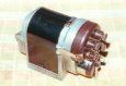
Once the magneto has been stripped and the armature is removed it can be seen that it is made up of two ends, one of which usually houses the condenser, and a centre laminated core which carries the primary and secondary coil windings. Before dismantling the armature it is a good idea to mark the three parts so that they can be reassembled in the same order. This is particularly important if several armatures of the same type are worked on. Using a different number stamp on each one helps identify which parts go together. Mixing up the component parts will quite likely result in an armature that does not run true.....
IMPORTANT: Before actually taking the armature apart, have a good look at the old coil. Make a note of where the primary winding starts and finishes and where the HT connection to the slip ring comes out. This information will be needed later so that the newly rewound coil has them in the same places. Also note the length of these connections – we always make them too long to start with and then trim to length when the winding is finished. Remember that a picture speaks a thousand words. A drawing is good – a photo taken with a digital camera could be really useful later on. Obvious really but once the old coil has been removed, all that information is lost…..
Stripping away the old coil is usually quite easily carried out using a sharp wood chisel. This works well on original coils and some rewinds. More recently rewound coils using more modern varnishes are usually much more solid and may need to be drilled and/or milled to remove the old windings. Hold the armature in the vice jaws as lightly as possible - the armature is easily distorted if the vice is over tightened. Cut through the thin secondary winding with the chisel. You can also cut through the thicker primary winding but be careful not to go right through and damage the armature core. We usually unwind the primary winding by hand.

Notice that there are no vice guards on the vice in the picture. Normally this would be very bad workmanship but the vice shown has had the jaws ground down to produce a smooth finish thereby protecting the armature core from unwanted criss cross marks caused by normal vice jaws.
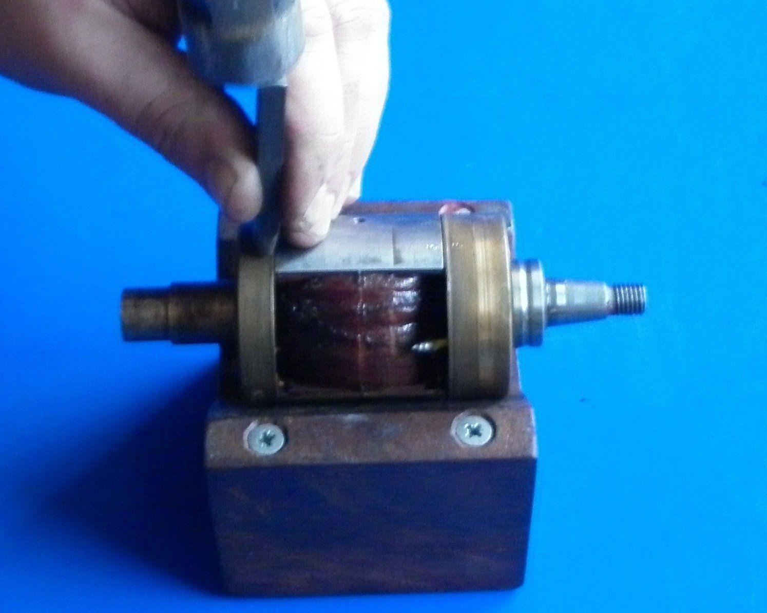
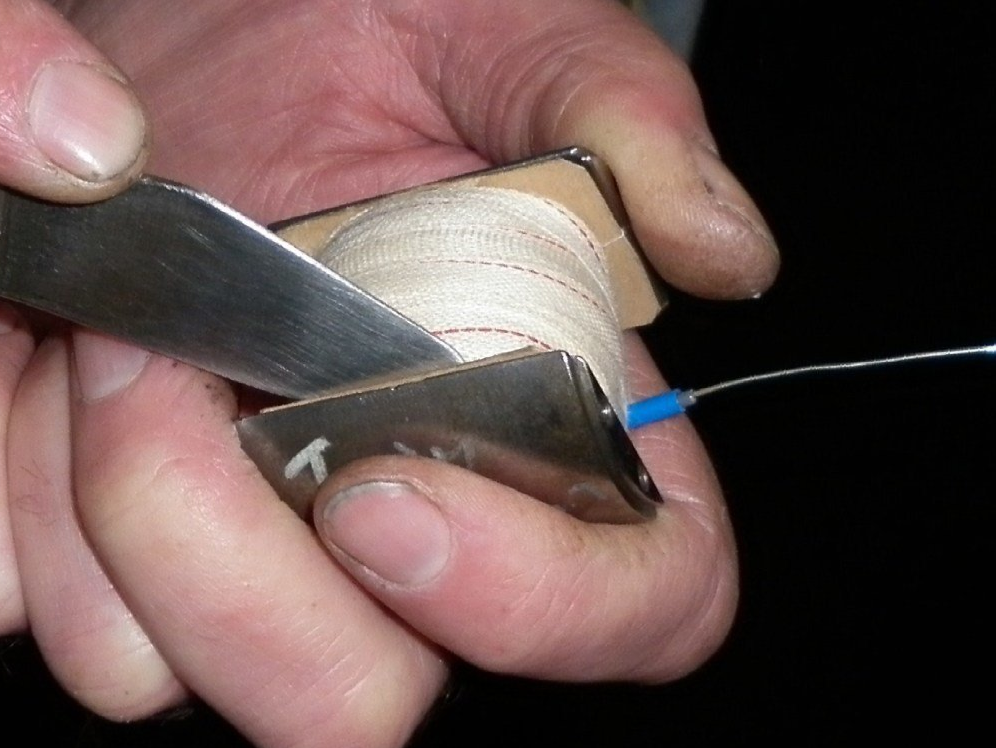
A clean cross sectional cut through the secondary coil will reveal the ends of each turn of the winding. This can often be achieved with the wood chisel but sometimes we use this Stanley knife blade holder and the fly press.
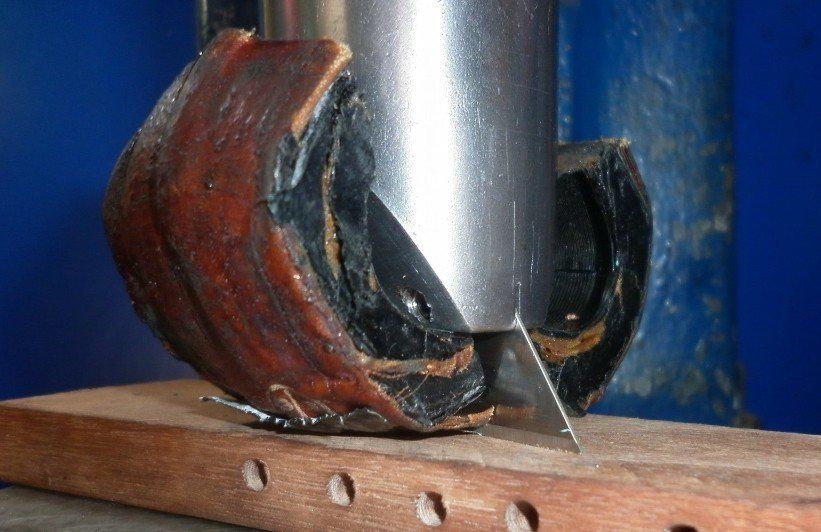
We then use a microscope to count the number of turns per layer and the number of layers. Multiply the two together to give an approximate figure for the number of turns in the secondary winding. A hundred turns either way is not too critical though we always use the calculated figure as a minimum when rewinding. For the primary coil, it’s enough to simply count the number of layers used.
Use a micrometer to measure the diameter of the wires used in the old primary and secondary windings to determine the gauge of wire to be used in the rewind. Record the results so that you don’t have to count again next time the same coil comes in!
Once the wire has all been removed, the chisel can be used to scrape off the majority of the old insulation and varnish and then the armature core is given a final clean up on the wire wheel. Use a file to round off any sharp corners otherwise there is a danger that they may cut through the insulation.
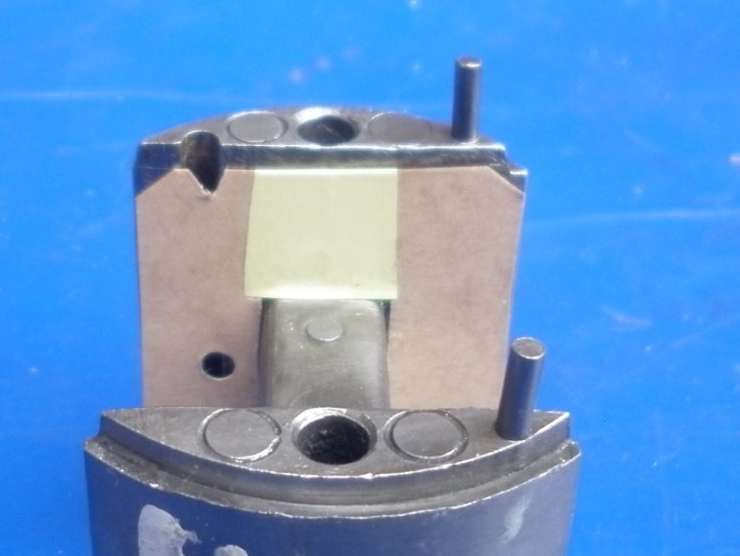
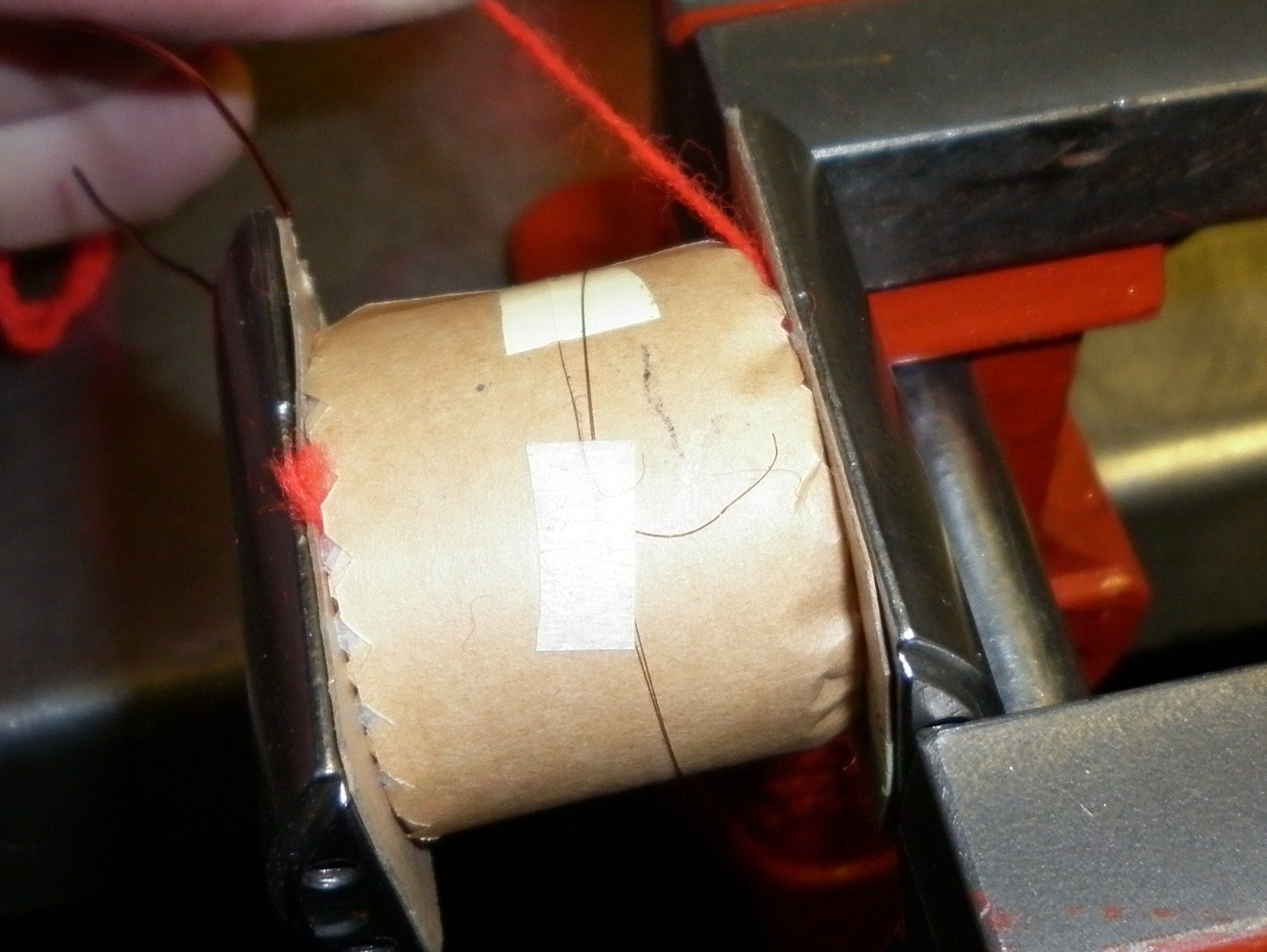
The sides of the core need to be insulated. The ends of this insulation are trimmed slightly inside the edge of the core so that the insulation will be clear of the armature ends when reassembled. Two small holes are punched in the side insulation to allow the ends of the primary wire through to the grooves machined in the armature core. V notches are cut in the end of the insulation over the grooves so that the wires can be folded over to clear the armature ends after the winding is completed. The scissor cut leading to the centre hole is covered with a strip of polyester tape. Fold the tape over at the top so that it goes down the other side of the insulation as well. This gives a double thickness.
This sequence of pictures shows how we do this.


The centre of the core is then covered with an insulation layer trimmed to width with dressmaker’s pinking shears. We don't know of anyone else who uses the pinking shears but we consider it a good idea because the triangles on the edges fold up the sides as shown. This helps to insulate the joint between layers of wire

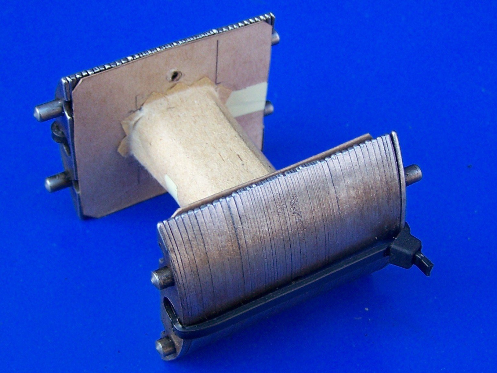
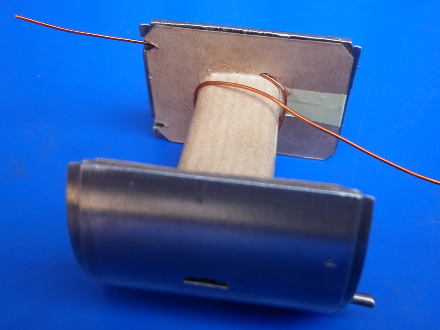
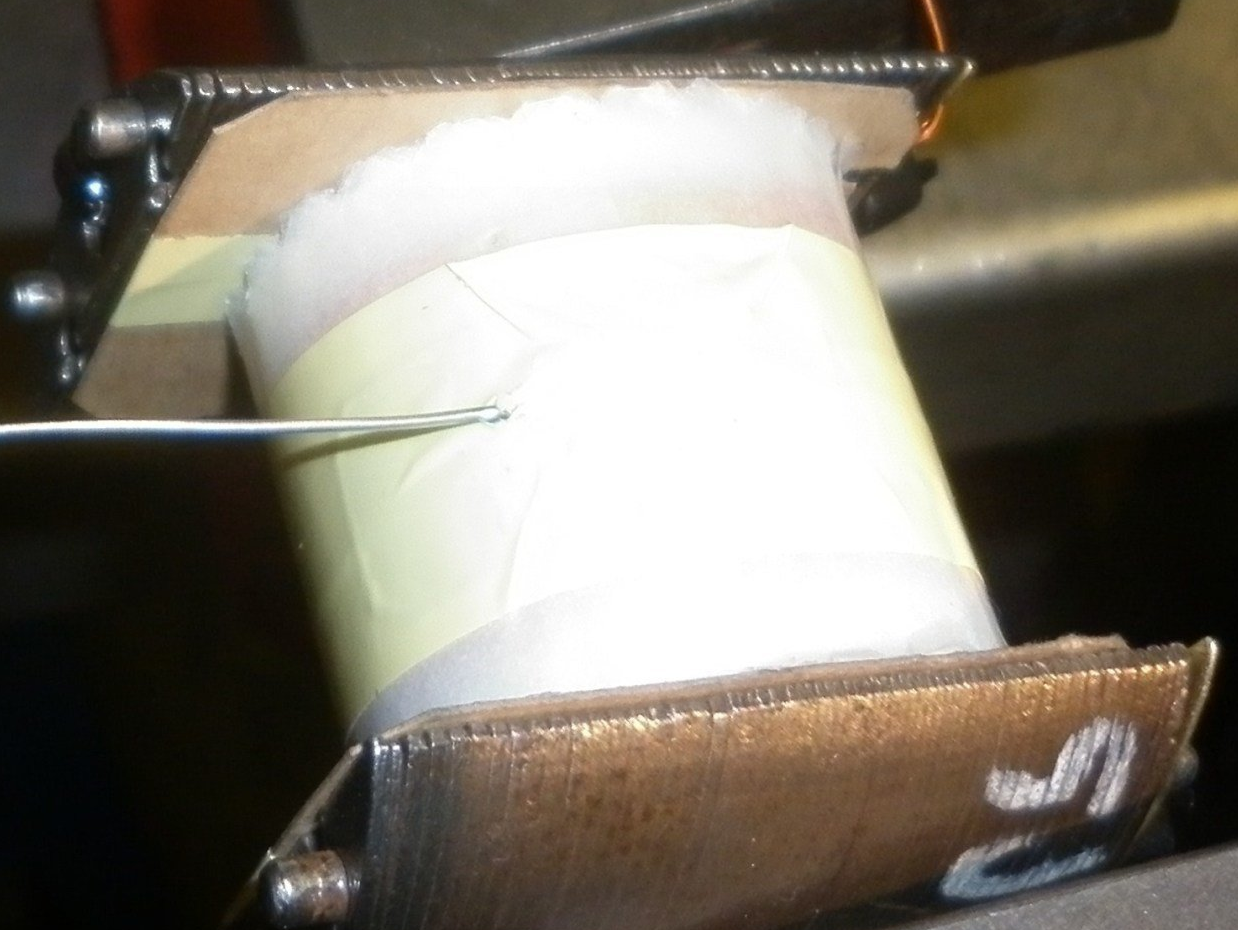
Primary winding involves passing the end of the wire through the hole in the side covering and revolving the core to make a layer of wire across to the other side. The direction of the winding should be fairly obvious in that the wire passes along the groove, through the hole in the insulation and then continues round the centre of the core with no U turns! Wire and insulation layers are interleaved until the required number of wire layers are completed. The wire turns cover the full width of the core and need to be kept close together without any crossovers. Polyester tape is used to hold the start of each layer of insulation and also to secure the last few turns of the final layer of wire so that the turns remain tight. Note in the third picture that the yellow sleeving for the end of the primary winding passes through the side insulation. The other piece of sleeving can just be slid along the wire which is the start of the primary winding . This wire will eventually be connected to earth anyway so insulation here is of less importance.


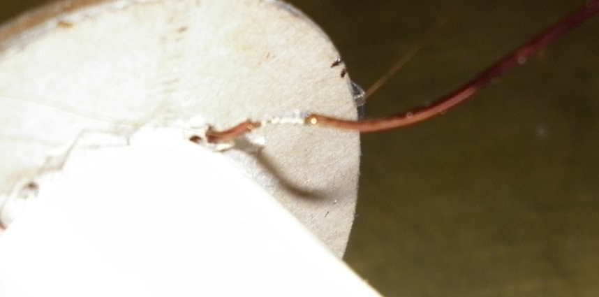
A section of the primary winding wire is stripped of its polyurethane coating, the start of the secondary wire wrapped around this area and then soldered. Look closely at the picture - the secondary winding can just be seen soldered to the primary - it's a very thin wire! The end of the primary winding is then fed through the yellow sleeving. Polyester tape is used to cover the joint and provide some mechanical support.
The secondary winding consists of interleaved layers of winding and insulation. The winding should continue in the same direction as that used for the primary winding. The insulation layers are again trimmed to width with the pinking shears but narrower this time so that they fit within the side cheeks without any turn up. The wire layers making up the first 5,000 or so turns of wire are started and finished approximately 3mm from the sides. Then, as the remaining layers are built up, this dimension is increased until the final layer has a gap of approximately 8-10mm on each side.
The final layer of the secondary is finished in the centre and covered with a double layer of insulation.

At this stage, the coil is very delicate. The layers will quite easily slide over each other. Be careful not to allow this to happen as the secondary wire is easily broken. We always wind a few turns of wool down each side of the winding. We don't know of anyone else who does this but we have found that it serves to tighten up the stack of layers a little.
The end of the secondary and a short length of tinned copper wire for connection to the slip ring are both soldered to a piece of self-adhesive tinned foil. A strip of polyester tape is pierced with a sharp point and fed over the tinned copper wire to both insulate and to help hold everything in place. The tinned copper wire spout is then insulated with high temperature sleeving – we use a double layer - again held in place with more polyester tape.


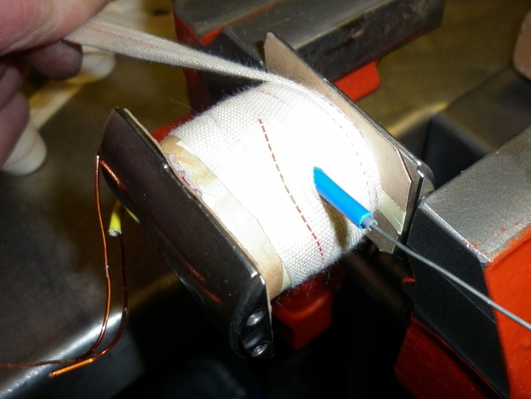
The coil is then wrapped with Egyptian cotton tape. This is followed by a layer of plain cotton tape and then a second layer of Egyptian cotton tape. The tape needs to be pulled tight but be very careful not to allow the layers to turn. It is a good idea to wrap the tape around the winding in the opposite direction to the direction the wire was wound. This way, if the winding does turn by accident, it will loosen the winding rather than tighten it resulting in a breakage. To finish off the wrapping up process, the end and then the edges of the tape are pressed down into the sides of the winding using a blunt knife blade.

Slide a length of insulation sleeving over the start end of the primary winding if you haven't already done it earlier, trim the ends to length and then it's time for the MOT - the Moment Of Truth! Do a final check for continuity from one end of the primary to the end of the secondary (tinned copper wire) and if all is well, the coil is then ready for the vacuum/pressure impregnation
process.
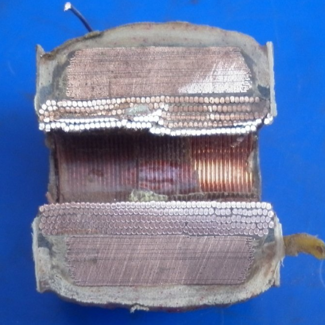
The following picture shows a sectioned coil. Before it was cut in half, it had already been through the vacuum/pressure impregnation process which holds everything together. We have included it here to illustrate what we have tried to achieve when winding the coil. Note the following:
- Side cheek insulation
- Thick wire used for the primary winding covering the full width
- Thin wire used for the secondary winding - narrower width which reduces even more as the winding progresses
- Wool pulled down each side resting on top of the primary winding
- The final layers of cotton tape pulled down the sides - made easier because of the zig-zag edges of the insulation layers
We will finish this page by answering some of the frequently asked questions:
What are the materials you use to rewind coils? Full details of all the materials used during the coil winding process can be found
here
Why don’t you use a modern day plastic sheet as insulation?
There is no doubt that modern plastics can be excellent insulators. However they cannot soak up the insulating varnish used in the vacuum/pressure impregnation process in the same way that presspahn and kraft paper do.
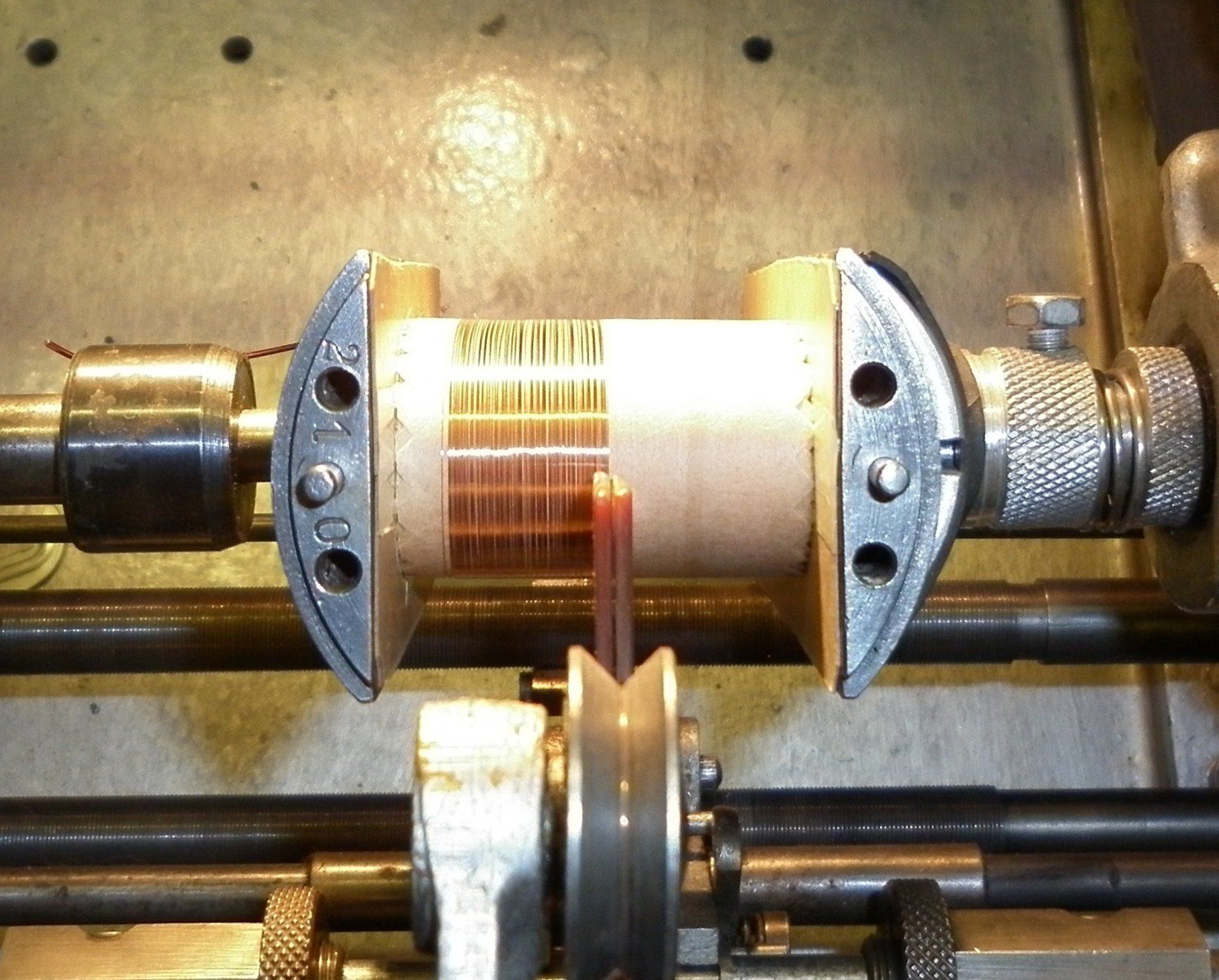
How fast should the coil winder go?
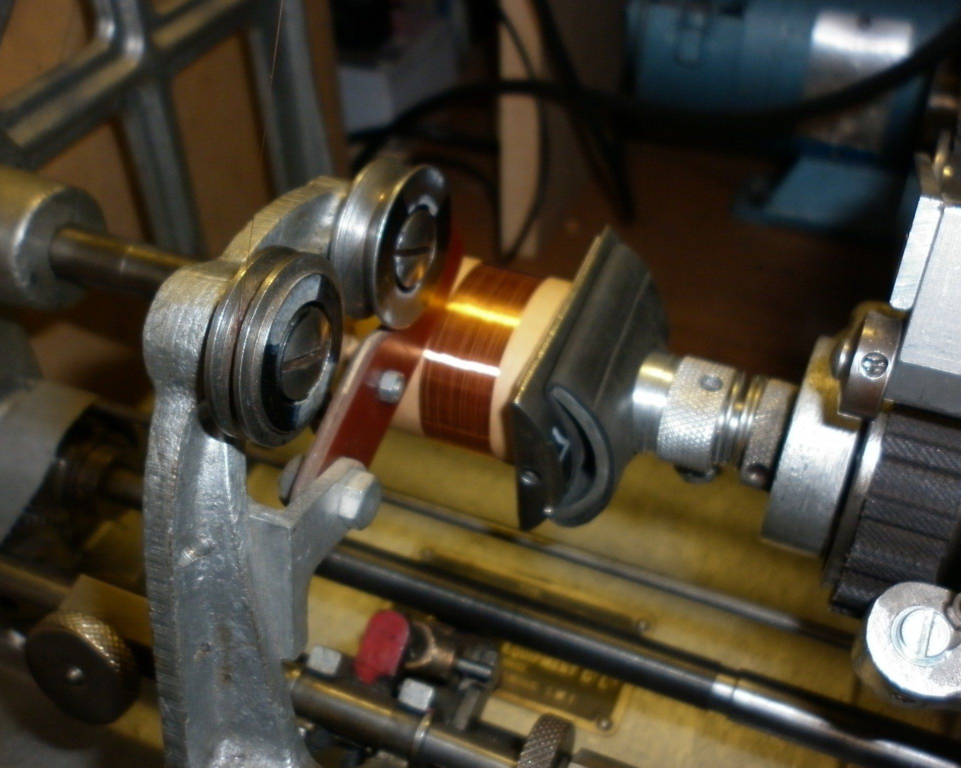
Well, it depends partly on the diameter of the wire but mostly on the shape of the coil. A round coil such as used on a Scintilla Vertex could probably run at about 700-750 rpm. Coils with square cores put a changing strain in the wire tension so have to go slower – a Lucas N1 would be ok at about 650 rpm. Some of the early magnetos have a core shape resembling that of a plank! On a Bosch D4 core as shown here, the winding speed would be down to about 140 rpm!

To be honest we had to measure these speeds to find out the actual figures so that we could answer the question properly. Normally we would be saying ‘I can go a bit faster with this one’ or ‘I’ll have to go really slow with this one’ and adjust the speed accordingly – there’s no substitute for experience!
Why scrape the polyurethane coating off the wire before soldering?
It's true that using 'solderable' enamelled copper wire means that the heat of the soldering iron will melt the coating allowing a soldered joint to be made to the copper underneath. This is fine when soldering two wires of similar thickness but when we solder the very fine secondary winding wire to the much thicker primary winding wire, we believe it to be a good idea to scrape the coating off the thicker wire. It makes it quicker and easier to solder the joint thereby putting less strain on the secondary winding wire.
How much tape is wound over the top of the wire/insulation wires? Start in the middle, wind to one side and pull tightly down the side of the winding. Then wind across to the opposite side and pull down the side there as well. Finish by winding back to the middle. Each turn of the tape needs to cover half of the previous turn. Achieving this is made easier by referring to the red line woven along the centre of the tape. This is followed by the plain cotton tape. Start in the middle again, off to one side, over to the other side and back to the middle again. No need to pull down the sides though. This is repeated with the final layer of Egyptian cotton tape. So that amounts to two side to side passes for each of the three tapes.
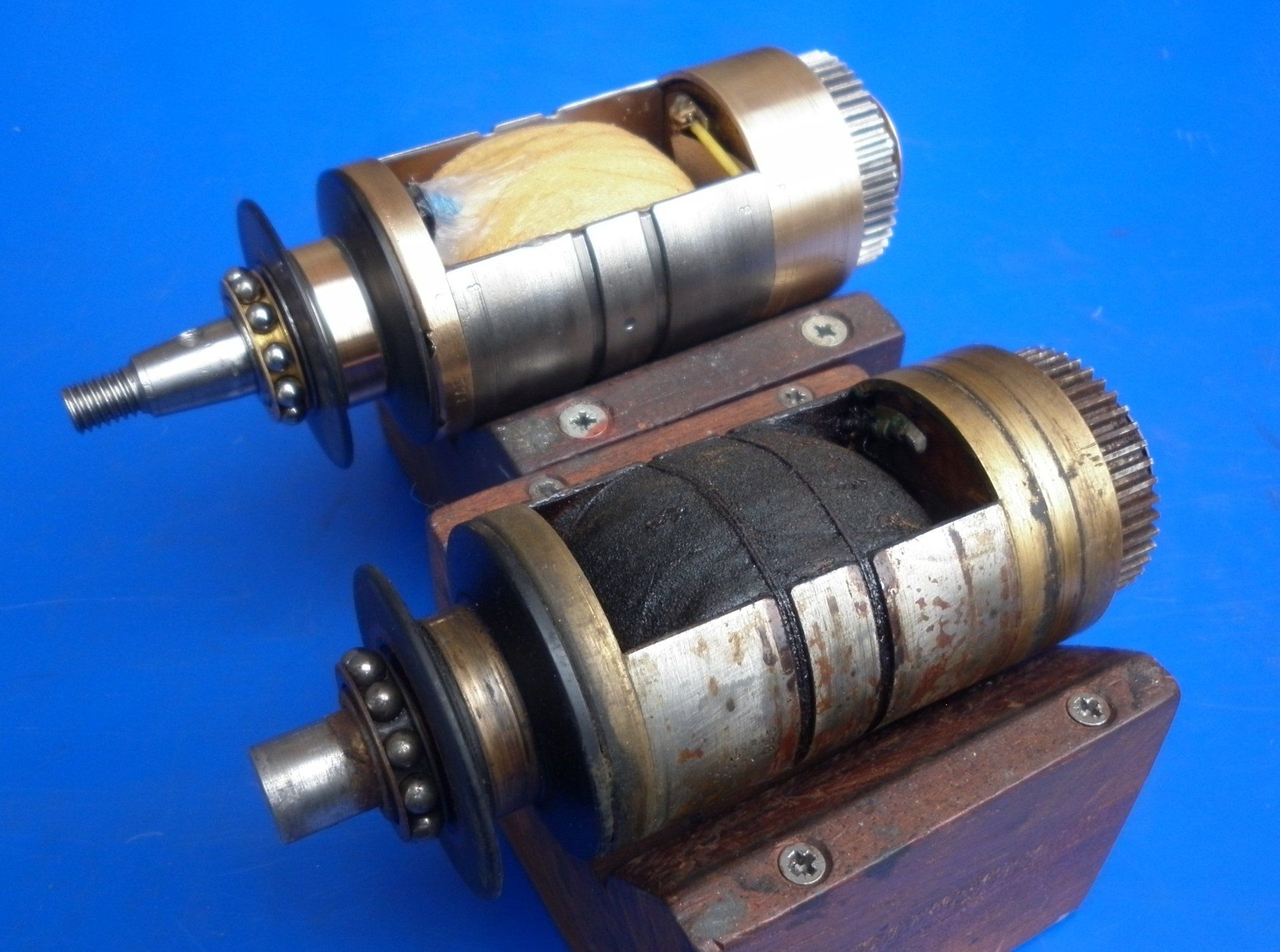
What is the reason for binding string around the core?
In the early days it was common to see this on large armature cores such as these Bosch DU4s. This was essential because the coil windings were not at all solid and without the binding, the coils would be flung out under centrifugal force. This would strain the secondary winding in particular and quickly result in a broken wire. The binding is not necessary when using modern varnishes and vacuum/pressue impregnation as the coils are considerably more solid and not free to move.
Are all coils wound in the same way?
No, there are many, many variations but the general principles are the same - what we have described here is only a start!