Maglita Magnetos
During WWI, the Admiralty was concerned about supplies of magnetos for aero-engines for the Royal Naval Air Service. They encouraged several British companies to develop magnetos including Morris and Lister of Carlton Works, Lockhurst Lane, Coventry. They became the ML Magneto Syndicate Ltd. and produced all types of magnetos for 4 and 6 cylinder cars, light cars, motor cycles and aeroplanes. One of their more innovative designs used for motorcycles was called the Maglita and was described as ‘a combined direct current generator and inductor magneto’.
The earliest references we have found to a Maglita are 1923 – fitted to the Velocette Model G and the Royal Enfield 250cc Model GC. The ML Magneto Syndicate was sold to Joseph Lucas Ltd in 1930 and Lucas continued to market the Maglita, now with the Lucas logo on the cover. The latest reference we have found to a Maglita is 1939 – fitted to 250cc Rudge machines. Unless you know any different?
Nowadays, Maglitas are much derided and often described as able to either produce a spark or supply the lights – but not both together. In actual fact they were probably a revelation in their day bearing in mind that they replaced acetylene lighting! Admittedly the generator output is not very large – most problems are caused by using a headlamp bulb with too high a wattage. Properly overhauled, the Maglita can give reasonable results.
During the Maglita’s production span, there were many variations. To illustrate this, the following notes have been extracted from period literature.
ML Magnetos Instruction Book - Types E & F Maglita combined ignition and lighting - not dated but makes reference to '...during the first part of the 1923-24 season......'
Both E and F types
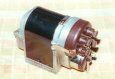
- Easily distinguished from later types as these have an aluminium cover held in place with two spring clips
- No cut out fitted in the Maglita itself - supplied with a semi-automatic cut out fitted in a separate switch box. The rider needs to press the button on a switch box to close a contact between Maglita and battery. That contact automatically opens when the engine is stopped
- Two types are listed: Type E1 (or F1) for single cylinder and E2 (or F2) for twin cylinder
From Folder No 513 – THE M-L “MAGLITA” - dated August 1925
Both FC and FB types
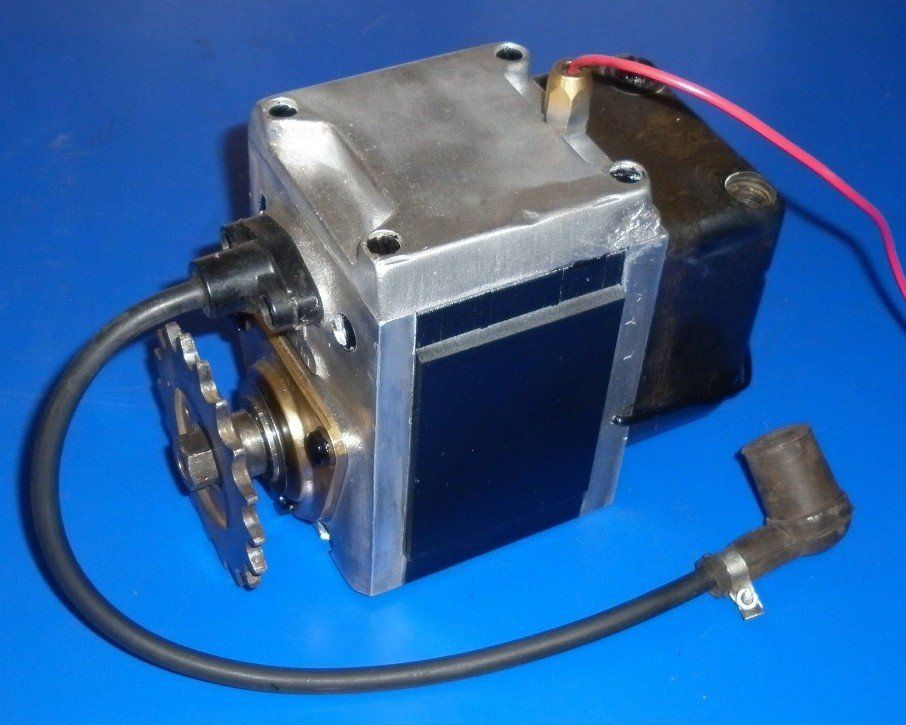
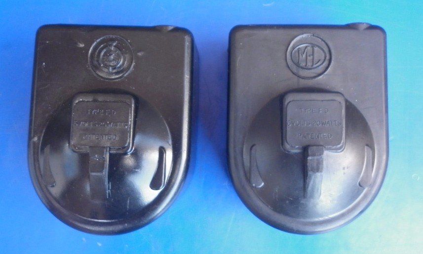
- Pictures show moulded bakelite cap with ML logo, held in place by wire clip passing from side to side across the front of the moulding
- Complies with the dimensions fixed by the British Engineering Standards Association (BESA) for “K” type magnetos
- The centre height can be reduced from 45mm to 35mm by removing the base plate
- No cut out fitted in the Maglita itself - supplied with a semi-automatic cut out fitted in a separate switch box. The rider needs to press a button on the switch box to close a contact between Maglita and battery. That contact automatically opens when the engine is stopped
Type FC
- For engine speed drive on all single cylinder engines
- Can be supplied specially wound for driving at half engine speed but lighting output reduced in the ratio of about 3:2 – should only be used on small engines of about 250cc with a normal top gear ratio of 6:1 or lower
- Can be supplied with extended base fixings as specified by BESA for the “M” type magneto
- Overall length 150mm
- Weighs 9lb
- Will generate 3 to 3½ amperes at normal road speed
Type FB
- For half engine speed drive on engines up to 350cc capacity
- Differs from FC in that wider magnets and a longer armature are employed – all other parts are identical
- Overall length 160mm
- Weighs 10lb
From Instruction Book No A540 – ML ALL-BRITISH MAGLITAS Types FB and FC Serial prefix “E” - dated May 1926
Both FC and FB types
- The battery is rated at 4 volts 10 ampere hours BUT, quote: ‘Messrs Rudge-Whitworth have also supplied a number of 6v sets for export’
- Recommended head lamp bulb is rated at 2 amperes, tail lamp at ½ amp – 2 ½ amps at 4v = 10W
- Spare parts list shows head lamp bulb – 4 volt, 8 watt, and Pilot, Sidecar or Tail lamp bulb as 4v 2W
- Keep the points gap set to 0.010”
Type FC
- Suitable for engine speed drive on either 2 or 4 stroke engines
- Gives an output of 3 to 3½ amperes at a speed of 1500 rpm
Type FB
- Intended for running at half engine speed
- Will give about 2 amperes at 800 rpm on the Maglita, 1600 rpm on the engine
From Leaflet No 600/1 ML HOW YOUR MAGLITA WORKS – Types FD and FE Serial Prefix E – dated Sept 1930 (NOTE: On the final page of this leaflet, the address for the M-L Magneto Syndicate Ltd has been over stamped with JOSEPH LUCAS – Lucas acquired ML in 1930)
Both FE and FD types
- Includes an automatic cut-out of a centrifugal type carried in a circular case forming part of the armature spindle.
- The electrical characteristics of the two Maglitas supplied during the 1929 and 1930 seasons are shown as graphs which now indicate outputs at 6v.
- Makes mention that Rudge Motorcycles will be fitted with double filament head lamp bulbs for 1930
Type FD
- Supplied principally for 350cc engines and solo motorcycles
- From the graph, output 2/3 of the above so 16W
- 2 ampere bulbs should normally be used – at 6v, this equates to 12W
Type FE
- Larger machine and generally fitted to 500cc engines and sidecar work
- From the graph, output 24W at 6v at 2000rpm
- 2.5 or 3 ampere bulbs may be employed – at 6v, this equates to 15 or 18W
From Instruction Booklet No 203A – “MAGLITA” COMBINED LIGHTING & IGNITION EQUIPMENT – not dated but now published by Joseph Lucas Ltd
- Recommended head lamp bulb is rated at 12/12W, tail lamp at 3W and Panel lamps at 0.525W
- Wiring diagram depicts a 6v battery
Other observations
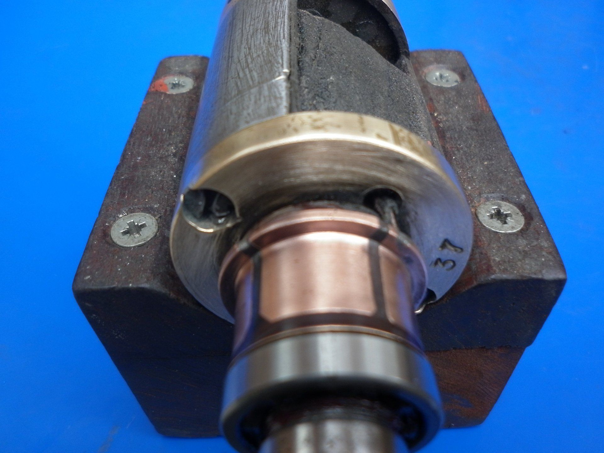
- The earliest Maglitas have a pair of magnets on each side – four in total. Later Maglitas only have one magnet on each side.
- Steel drive shafts are most common though some early Maglitas have brass drive shafts
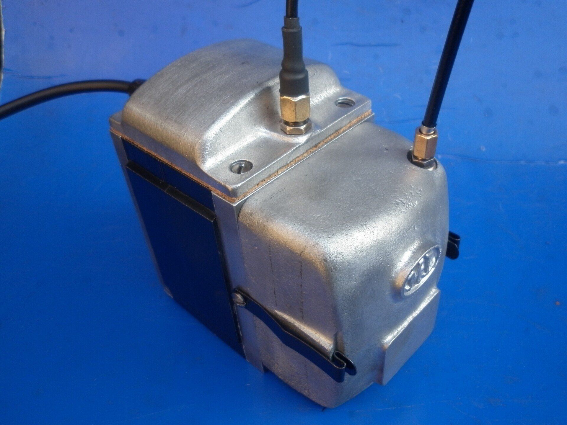
- Some Maglitas were fixed via four threaded holes in the base. Rudge used a special top cover with ‘ears’ for a forked clamp on each side. Interestingly, this was not simply a case of fitting a different top as the Rudge Maglitas have a plain base with no threaded holes.
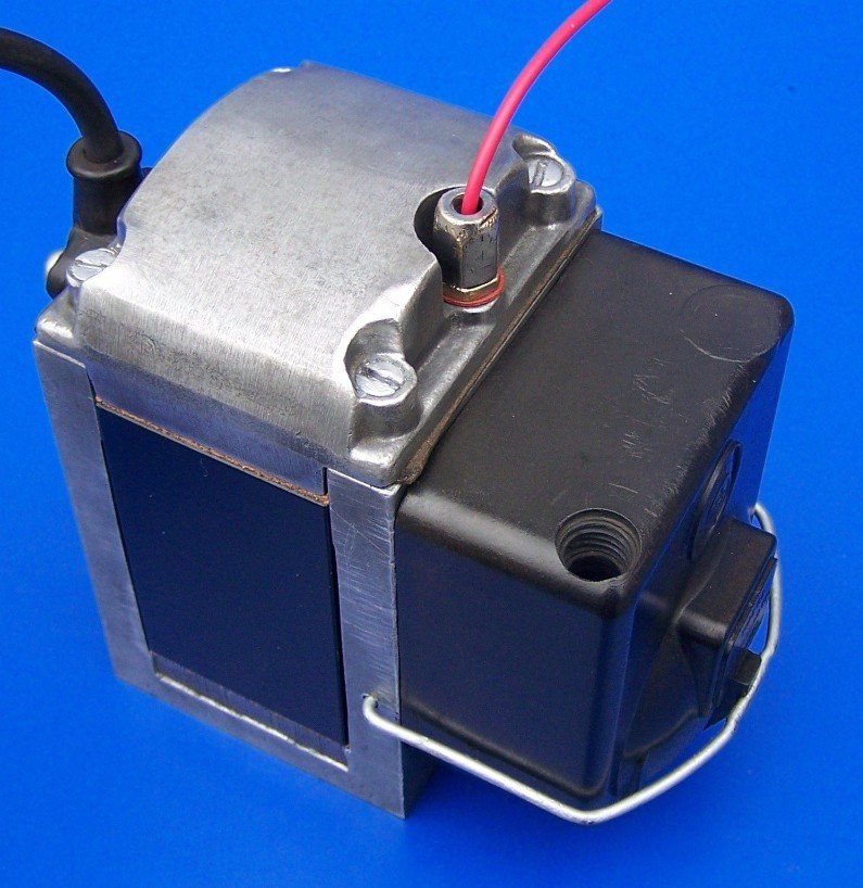
- Most Maglitas we see nowadays use a bakelite end cover held in place with a single wire clip. However, the very early Maglitas were fitted with an aluminium cover held in place by two separate hinged spring clips on the sides of the body - see picture at the top of this page. The aluminium and bakelite covers are not interchangeable.
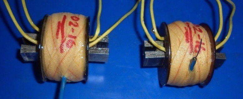
- On some Maglitas the HT outlet is on the end above the drive shaft - horizontal. On others, the HT is on the top cover - vertical. This means the coil needs to be wound slightly differently.
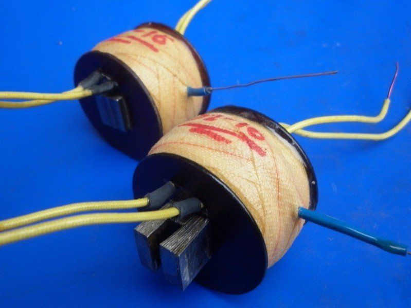
- There were variations in the way the coil was mounted resulting in different shaped coil laminations.
- The armature commutator has four brass segments but only two are used. These are soldered to the two ends of the one and only armature coil winding. The insulation between the commutator segments is softer than the brass and would wear at a faster rate than the brass segments. To prevent this happening, the two unused brass segments ensure that the brushes rub on a common material for the majority of its path.
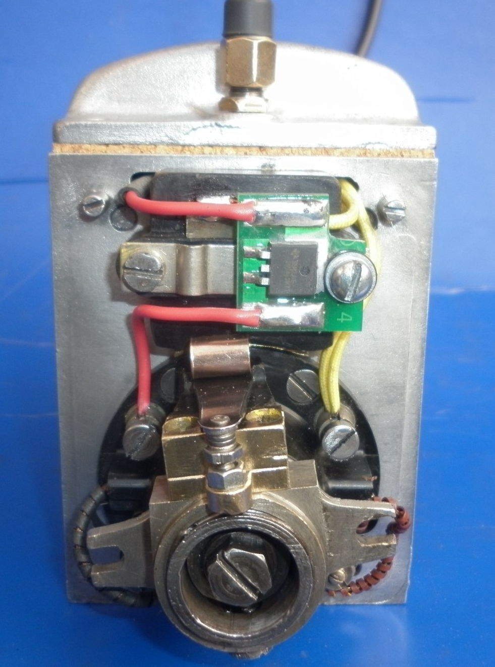
Maglita Cut-out
The dynamo output from the Maglita needs to be fitted with a switch which disconnects the dynamo from the battery when the engine is not running. Failure to do this will result in a flat battery. Various models of Maglita used a variety of cut-out types. Early ones were literally a manual switch operated by the rider. Some used an electromagnetic relay type of cut-out. The final designs used a centrifugally operated mechanical switch mounted in the end of the armature. In all types of Maglita which we overhaul, we replace the original method with a very efficient modern day device now manufactured by The Magneto Guys and known as a Smart Diode Cut Out.
We have described Maglitas Types FB, FC, FD and FE but we have never seen a ‘Type FA’ Maglita or any reference to one in period literature. Have you?