Rewinding Rotating Magnet Magneto Coils
- This is definitely not the only way to do it. Take a look at newly rewound coils for sale on eBay – they certainly look different to ours so it is obvious that not everyone does them the same way.
- We are definitely not saying you MUST do it this way - other methods may work satisfactorily. What we are saying is that years of practise with thousands of successful coil rewinds has evolved into this method.
Once the original windings have been removed, the core and side cheeks can be cleaned up with the wire wheel. Sometimes the side cheeks slide over the laminated core up against a step, sometimes held there with a turned up lamination. Others are simply glued in place. Different manufacturers had different ideas. The side cheeks are often loose and it is all too easy for them to move during the rewinding process. It is very important to ensure that the spacing between the side cheeks remains as original. Failing to do this may result in a coil which is too wide to fit back into the magneto body!
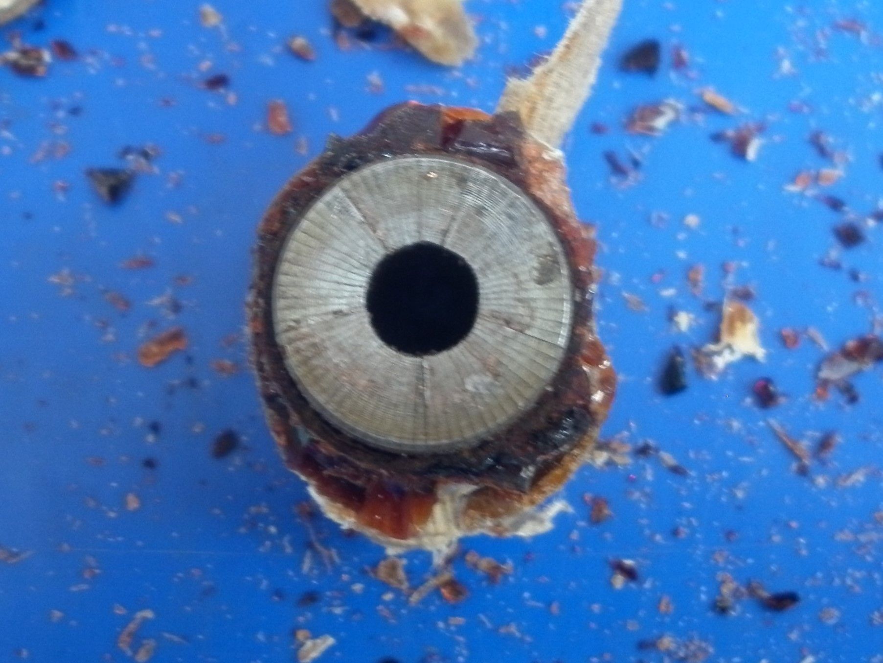
This core is from an Edison Splitdorf NS4 magneto. The brown side cheeks are the originals but when in place, they leave a rectangular section of the core exposed. We ensure adequate insulation by adding the two whitish side cheeks, made from presspahn, in a similar way to that done on the rotating coil cores.
A similar idea can be used to help glue together the pieces of a broken side cheek if no replacement is available.
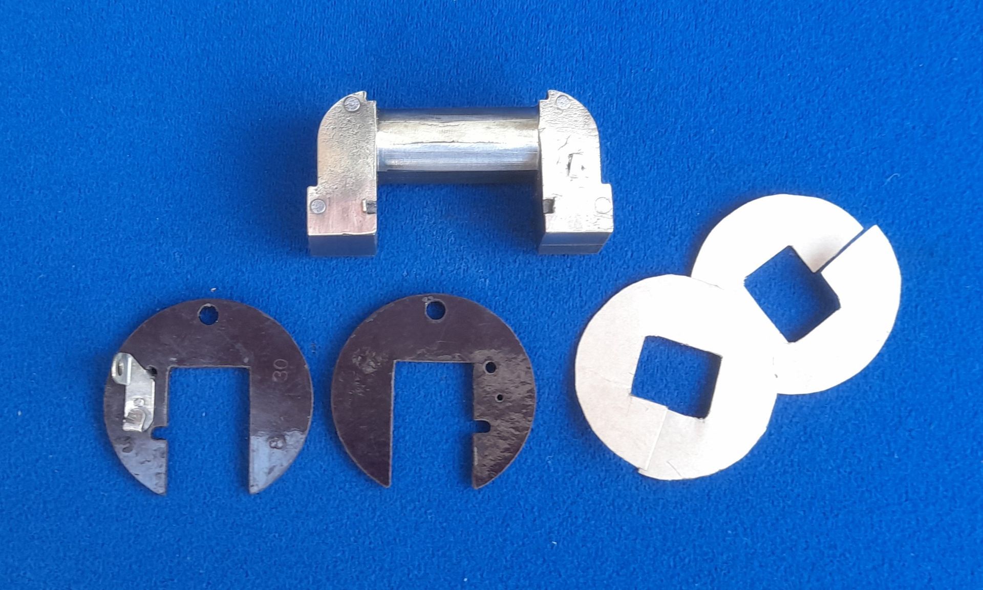
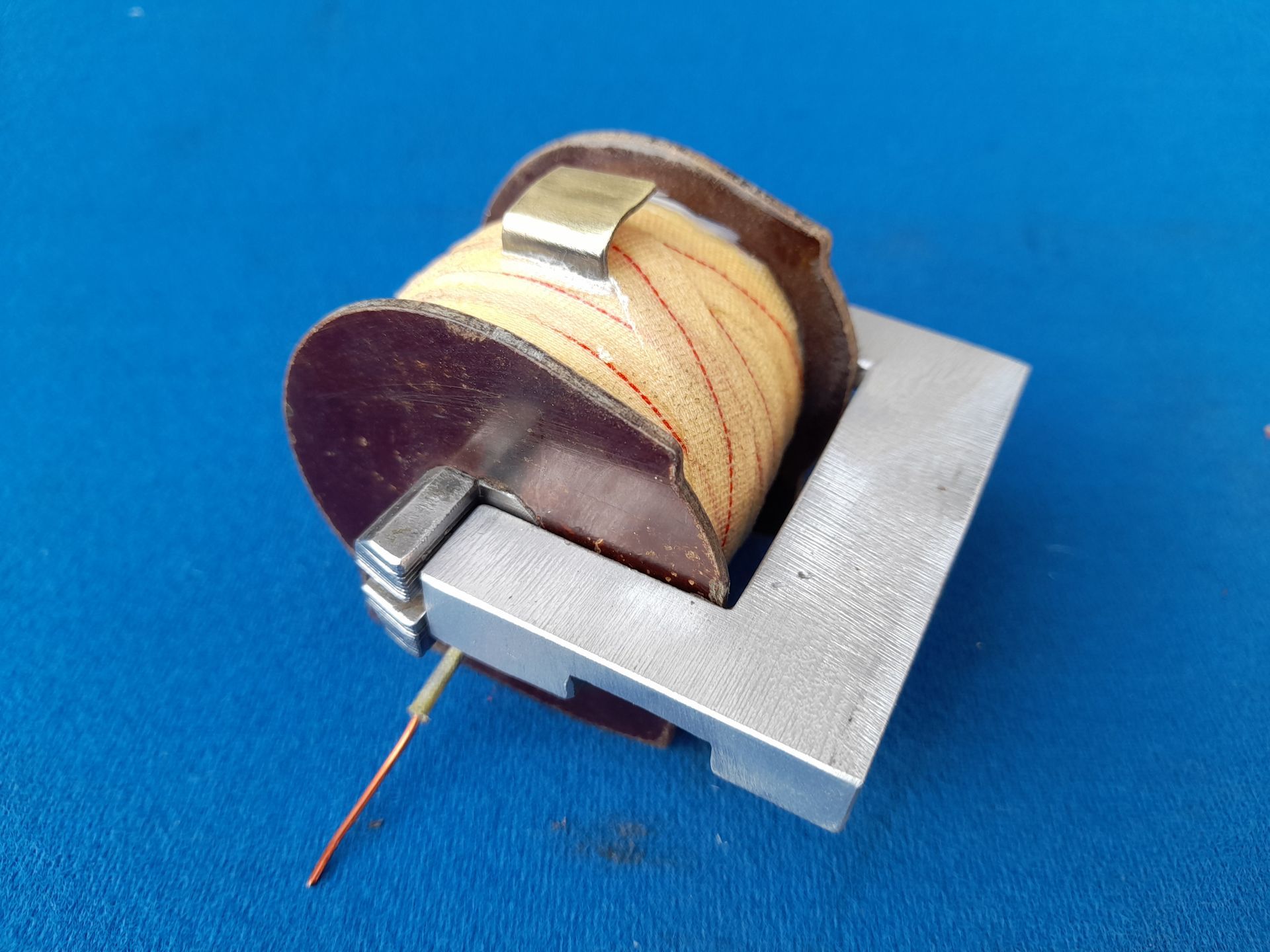
All of our winding machines hold the coils between pointed centres. This works well with the rotating coil magneto types but requires a slightly different approach for the stationary coils. This picture shows some of the adaptors we have made which fit onto the ends of the coil's laminated core.

The three pairs of clamps on the left were made for specific magneto coil cores. The fourth pair is a little more useful as they can be adjusted to suit a variety of different cores. They worked well but could be fiddly to get the core to run true in the winding machine as the core had to be taken out to get a screwdriver on the lock screw! Then we made the pair on the far right. The core can be moved side to side between the clamps as with the previous design but this one includes a dovetail slide to centralise up and down. This latest design works very well and all the others have become redundant now!
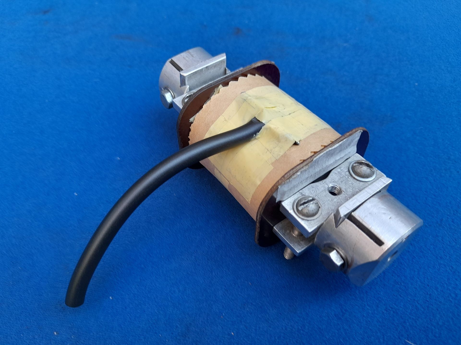
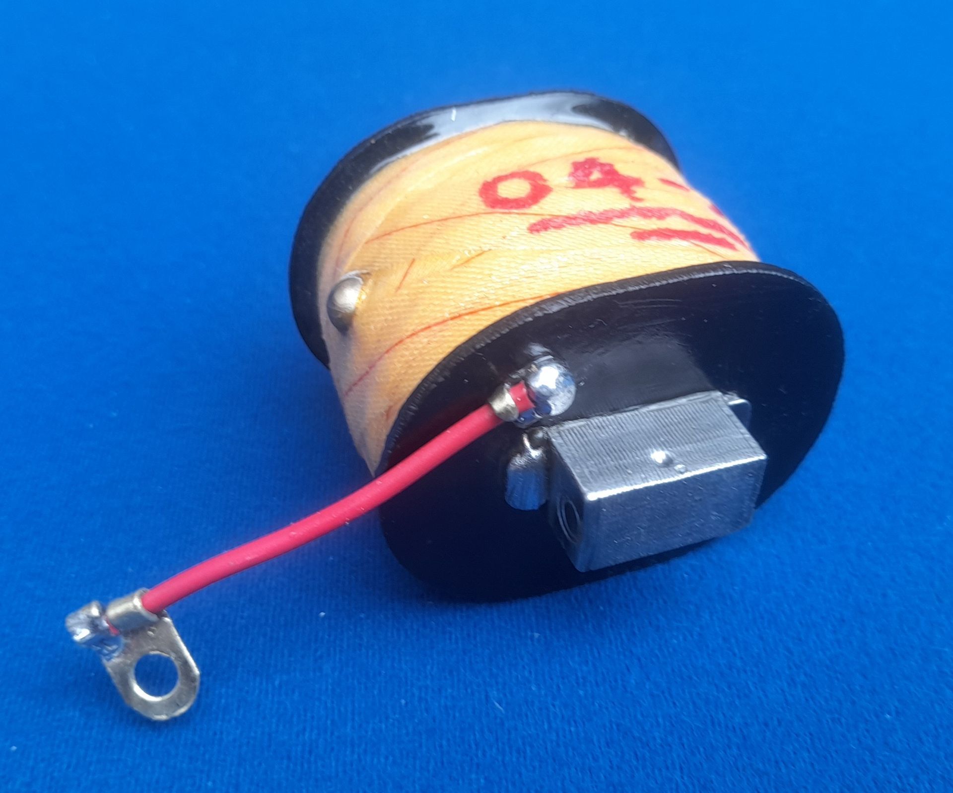
This picture shows the type of HT connector used on the Scintilla PN, MN and GN range of magnetos. The flat brass surface provides a contact point for a spring loaded carbon brush which is housed in the rotor arm. Obviously the brass contact needs to be positioned in the correct place on the coil so that it lines up with the carbon brush. It is also important that the gap in the brass contact is correct. Too short and the carbon brush will overhang the end of the rotor arm too much. Too long and the coil assembly will hit the rotor arm. It is easy enough to try the coil in the magneto body when the assembly has reached this stage - before the egyptian cotton tape is wound on. If necessary a new brass contact can be made to achieve the correct gap.
With some types of coils, it's worth checking the width over the side cheeks after the winding is completed and before putting the coil through the VPI process. At this stage, the windings are relatively flexible. If the side cheeks have spread slightly, they can be gently squeezed to allow an aluminium bracket to be placed over them. The bracket can be left in place during the VPI process.
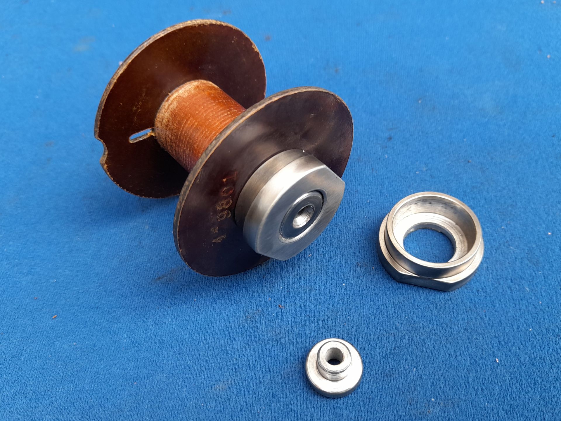
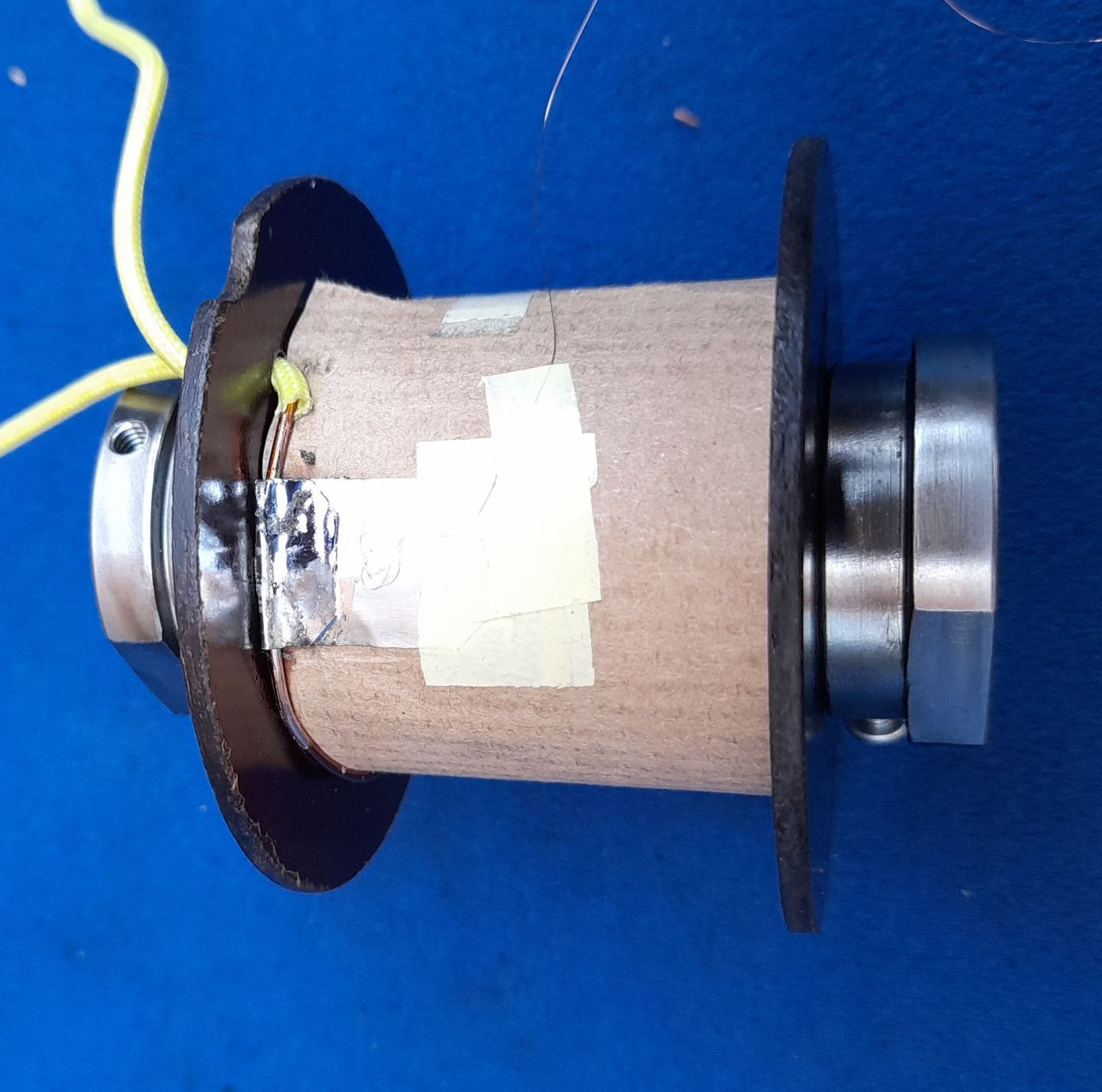
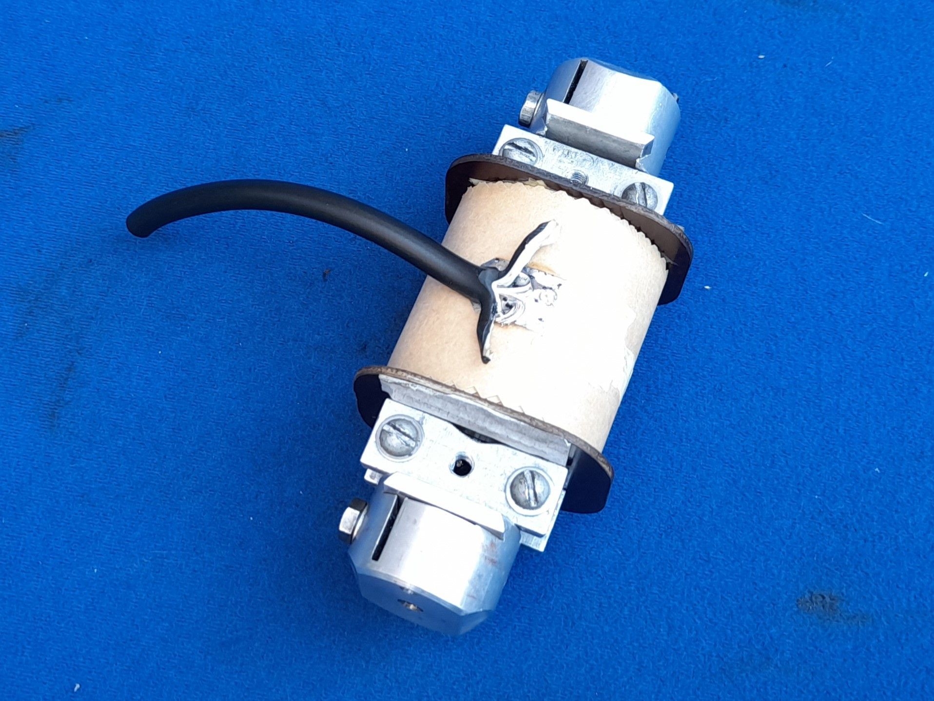
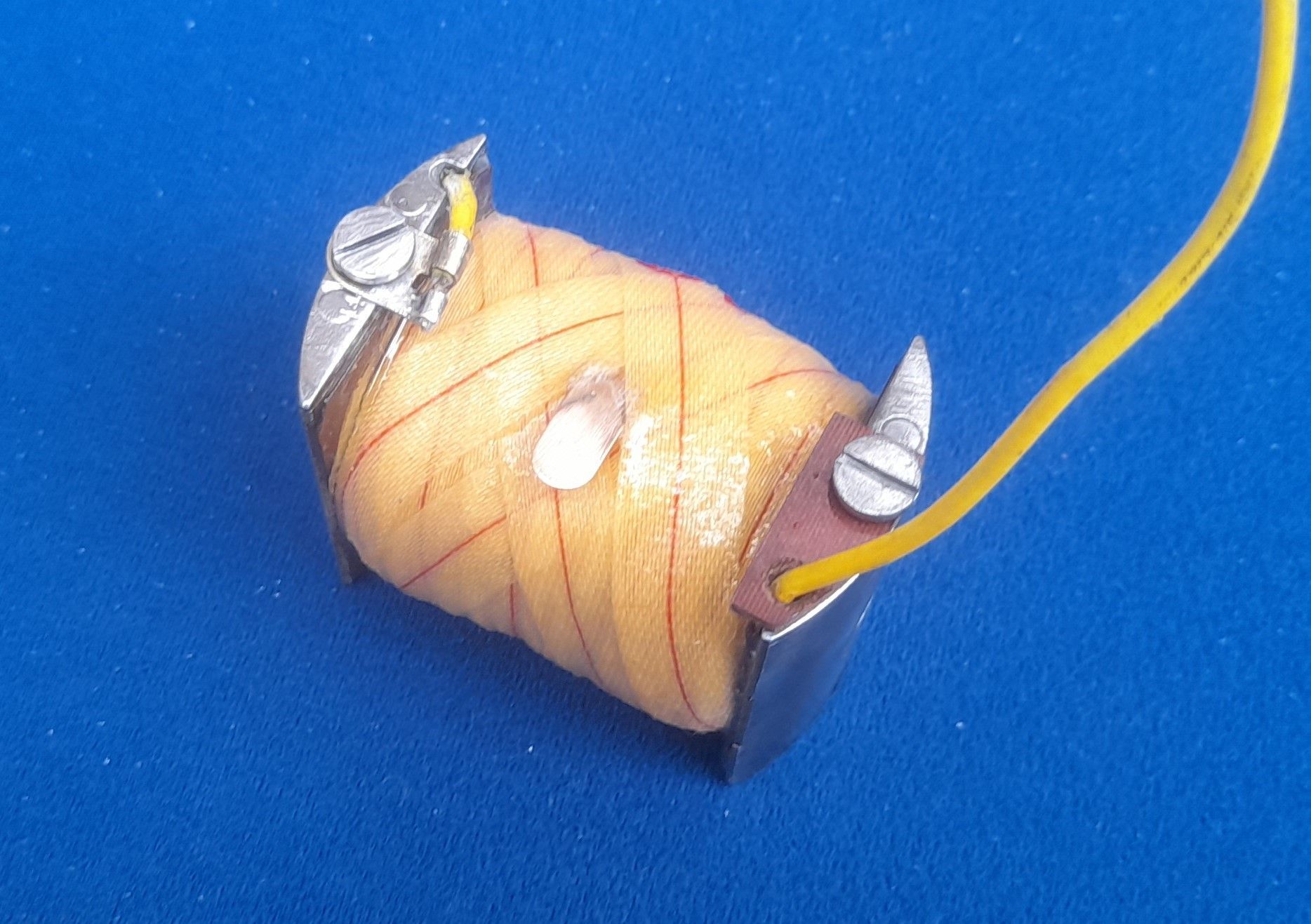
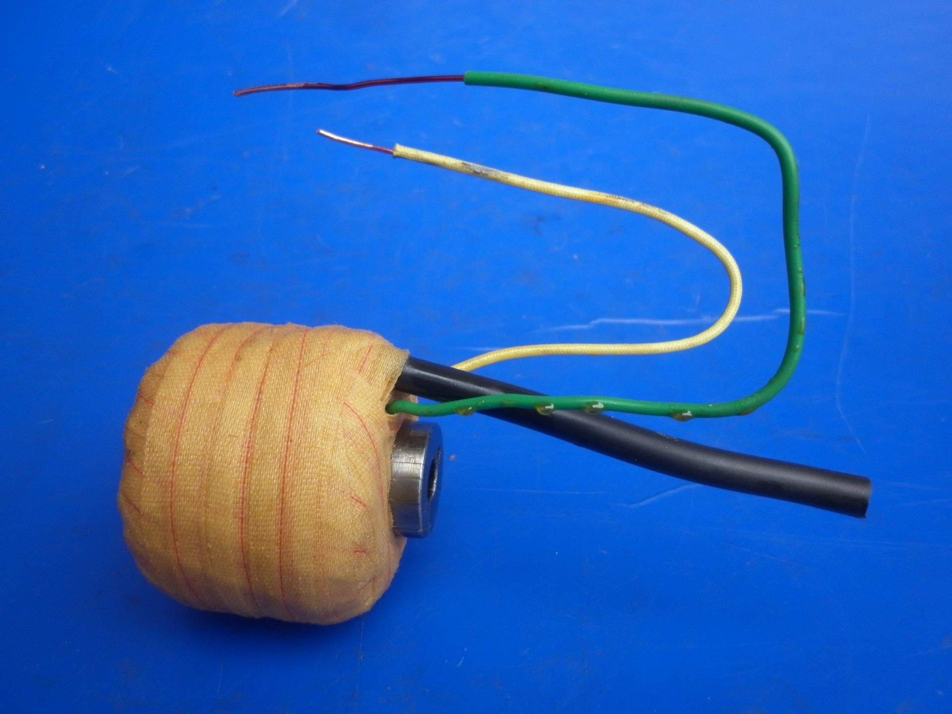
A brass tag is also used on the Lucas RF4 magnetos. It's an interesting design in that the core follows the same shape as those used in rotating coil magnetos. This one slides into a circular opening between the magneto pole pieces and is secured by a pair of screws which pass through the magneto body and screw into the curved sides of the core. Note the start of the primary winding earthed to the core and the long yellow sheathed wire which is the end of the primary which connects to the CB points and condenser.
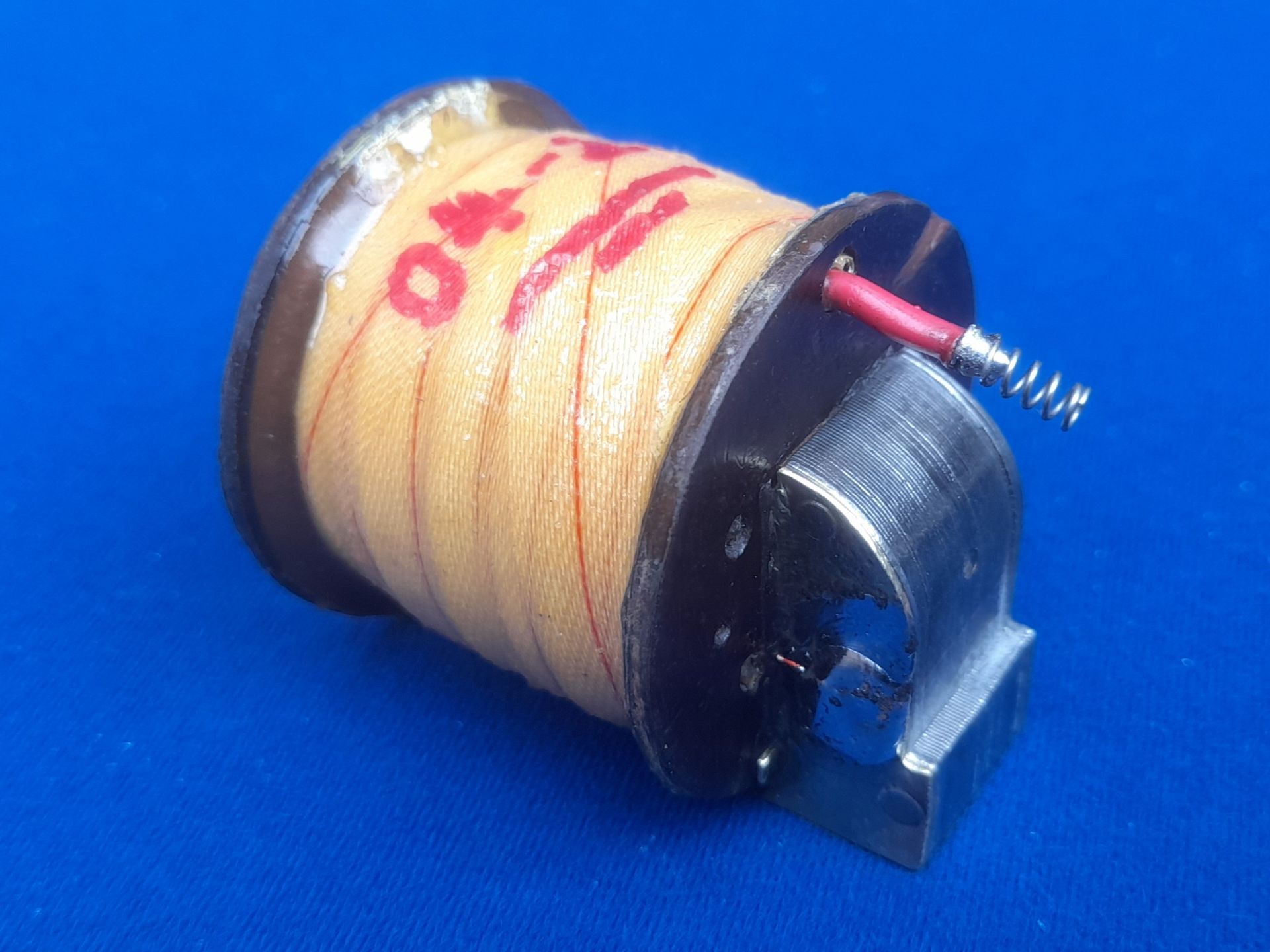
This coil is from the Splitdorf S2, S4, NS2 and NS4 range of magnetos. The HT connection passes through a relatively small diameter hole in the side cheek so it was never intended to be a heavy duty HT lead. We use ordinary 32/0.2 equipment wire for this. The spring on the end of the wire presses against a stationary brass plate. Nothing is rotating so there is no need for a carbon brush.
Some manufacturers used no side cheeks at all. It is of course possible to make a pair of side cheeks from tufnol sheet and fit them but rewinding the coil as originally intended makes for an interesting exercise. This sequence of pictures shows how we at The Magneto Guys rewind early Scintilla Vertex magneto coils.

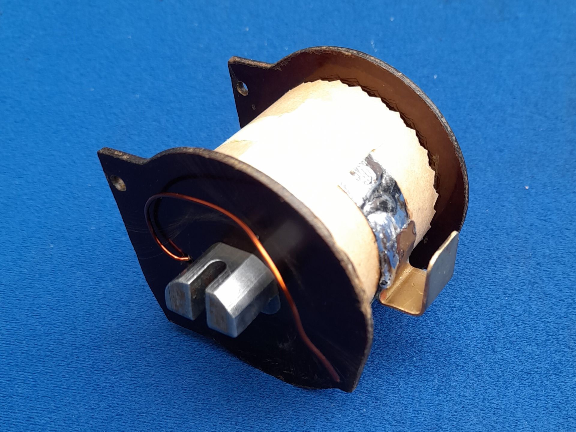
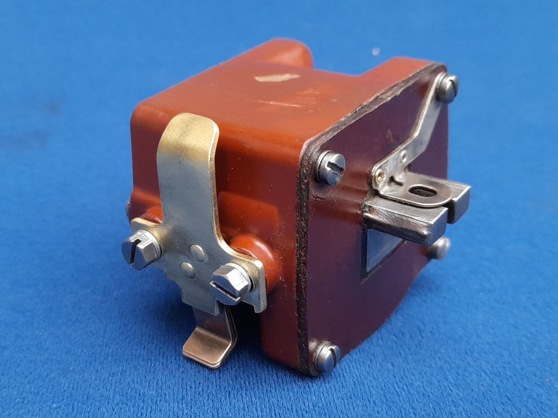
At the other extreme, some manufacturers (including Scintilla again!) produced fully enclosed coil assemblies. Usually, the enclosures incorporate the side cheeks to cover the ends. In some cases, such as this coil from a Scintilla MN6-3/4, the screws are removed and the coil pulled out
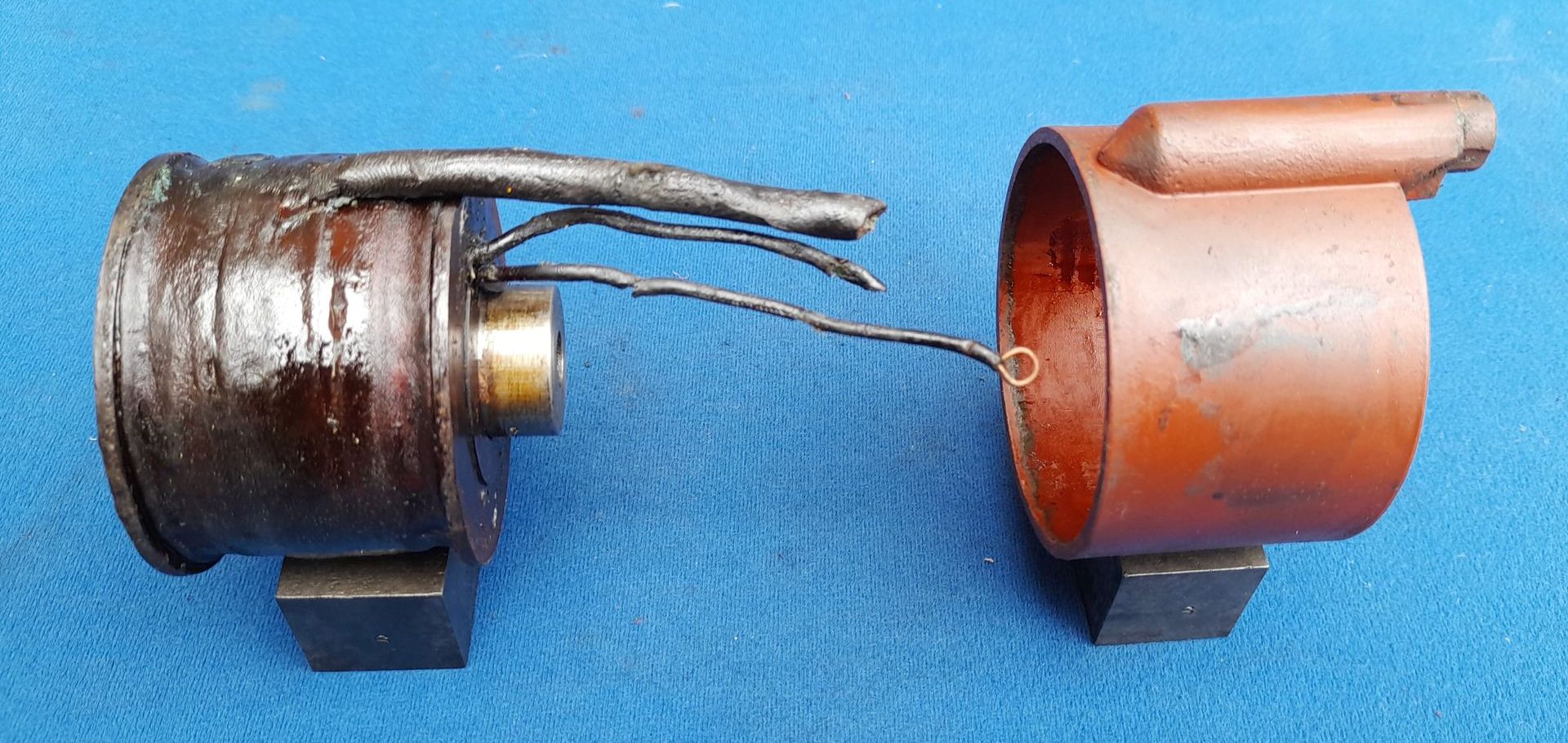
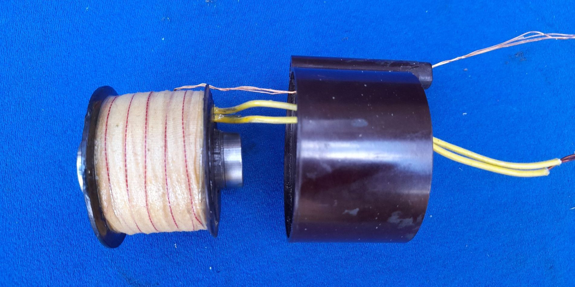
On others, such as this Scintilla Vertex coil, they are simply pressed together with a coating of shellac over the coil to hold everything together. They are often quite tight so it may be necessary to heat the assembly to melt the shellac and then press apart.
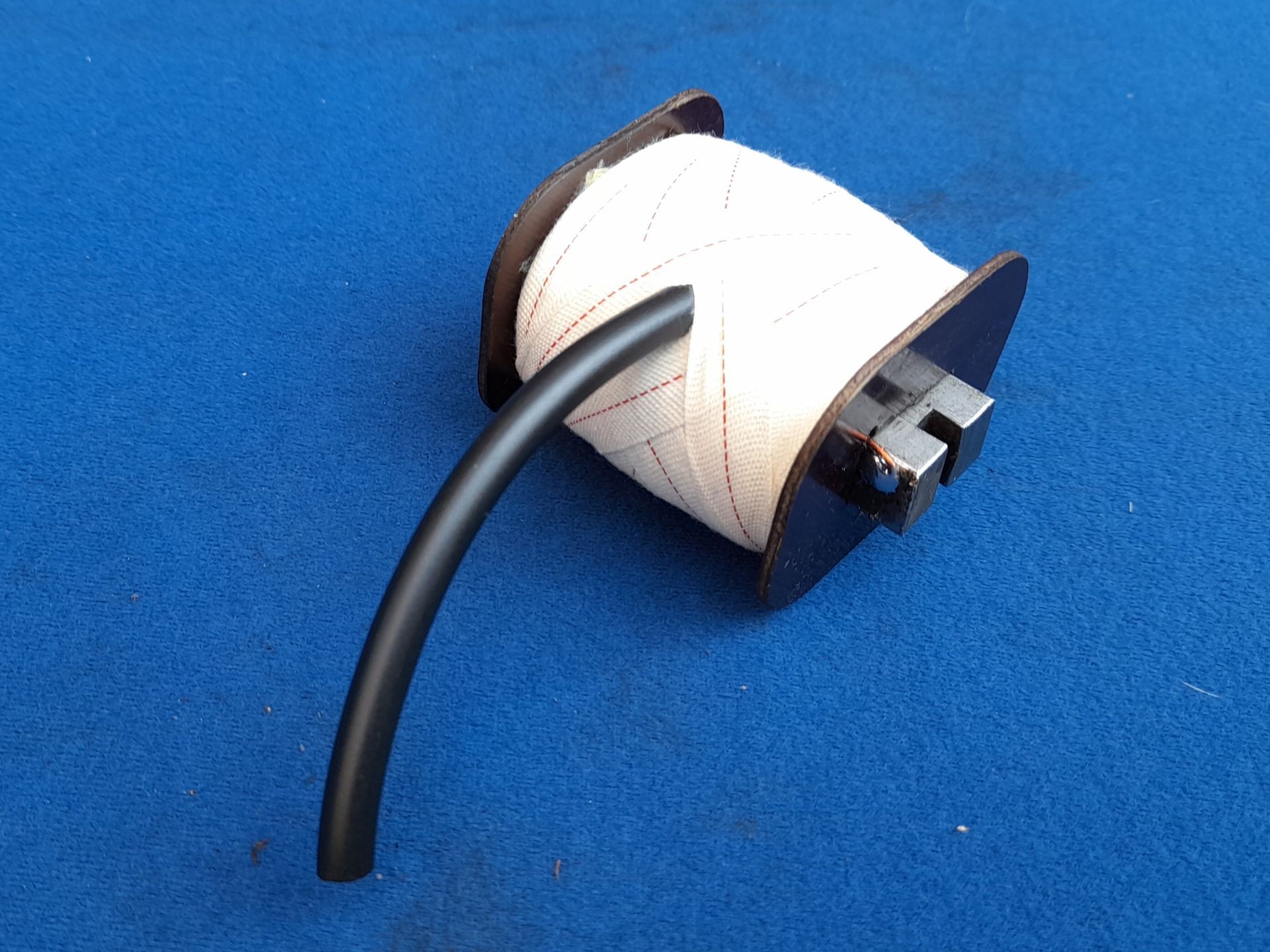
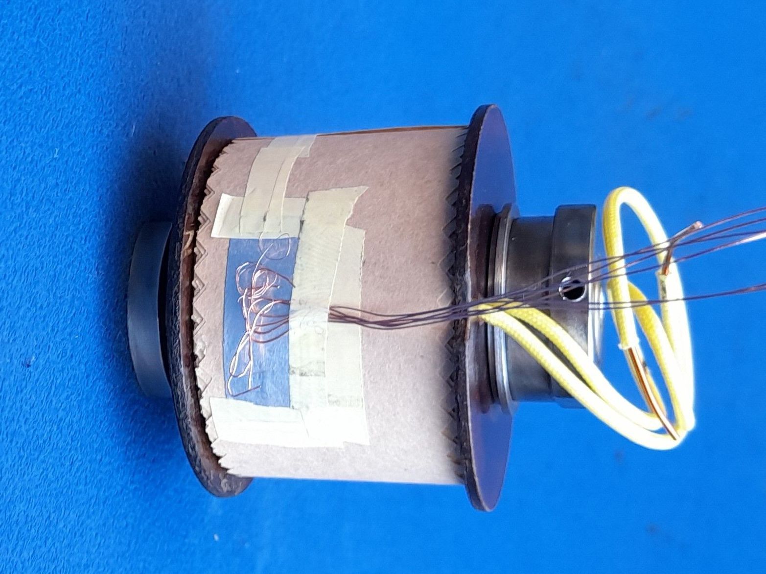
Once apart, the rewinding procedure is mostly as already described for other types. The only part of the procedure which is different is the way the HT comes out of the enclosure. The HT lead itself is made up with half a dozen strands of copper wire pulled from the centre of a piece of standard 7mm HT lead. These are soldered to the silvered copper foil pad as previously described. Once covered with polyeter tape, the coil is then ready for the egyptian cotton tape. It is not necessary to use as much as is normally used with 'open' coils as the enclosure itself acts as a very good insulator.
After the VPI process is completed the coil is inserted into the enclosure with the copper strands fed through the spout from the inside. This is made much easier if the wire strands are made much longer than needed. Once the coil is fully home, stick it in place with some silicone sealant. DO NOT use glue! Someone might need to take it apart again in the future!
The copper strands are then fed through an empty length of HT lead - again, made easier if they are longer than needed. Use more silicone sealant to stick the HT sleeve in the enclosure. The excess length of the wire strands is then trimmed off and a brass cap soldered in place. The original cap can usually be re-used but if necessary, a new one can easily be turned up in the lathe.