How a Magneto Works
The physics on how a magneto works is based on it's two basic types of component - wire coils and magnetic fields - and how they interact with each other. When one of these components is moved relative to the other, currents can be induced in the coils. Those currents can then be used to generate a high voltage able to produce a spark at the spark plug. Early magnetos used a stationary permanent magnet and rotating coils. As magnet technology and materials evolved, magnets got stronger and smaller. The smaller size of the magnets allowed the design to be changed so that the magnets revolved and the coils were stationary. Whichever design is used, the same basic principles of operation apply. Here, we will describe the stationary magnet/moving coil arrangement.
A list of the basic component parts just described. Click on the associated link to learn more about that specific part.
Primary coil: around 200 turns of relatively thick copper wire
Secondary coil: around 10,000 turns of relatively copper thin wire
Iron Core: primary and secondary coils are wound around a common iron core to maximise energy transfer efficiency between them. Very early magneto cores were made of a single block of soft iron. However this was not efficient due to the flow of eddy currents*
Bearings: usually a specific magneto bearing. Other types used include deep groove or self-aligning ball bearings. Many very early magnetos used bronze bushes.
Magnet: A permanent magnet is made from a material that can be magnetized and thereby creates its own persistent magnetic field. These include iron, nickel and cobalt and their alloys. Early magnetos used magnets in the shape of a horseshoe.
Pole pieces: A pole piece is a structure firmly attached to a magnet's pole, thereby extending the pole of the magnet. It is shaped to fill the gap between the stationary magnet and the rotating armature. It's main function is to direct the magnetic field produced by the magnet. The pole pieces, made of soft iron, are also subjected to the unwanted effects of eddy currents*.
*Eddy currents. Made of soft iron, the core and pole pieces can concentrate the magnetic magnets lines of magnetic flow. However, they are also a conducting medium which, when experiencing a varying magnetic field, will allow electric current to flow in them. These 'eddy currents', as they are known, are an unwanted source of inefficiency and waste heat generation. In order to minimise their conductivity and therefore the eddy currents that can flow in them, the core and pole pieces are made from laminated sheets of soft iron. This has the effect of increasing their electrical resistance and therefore reducing the current flow.
The permanent magnet has a magnetic field around it which can be thought of as a mass of 'lines of magnetic flux' which run from the magnet's North pole to it's South pole. These lines of magnetic flux flow easily through the iron laminations which are all arranged to provide an easy continuous circuit for them to flow round.
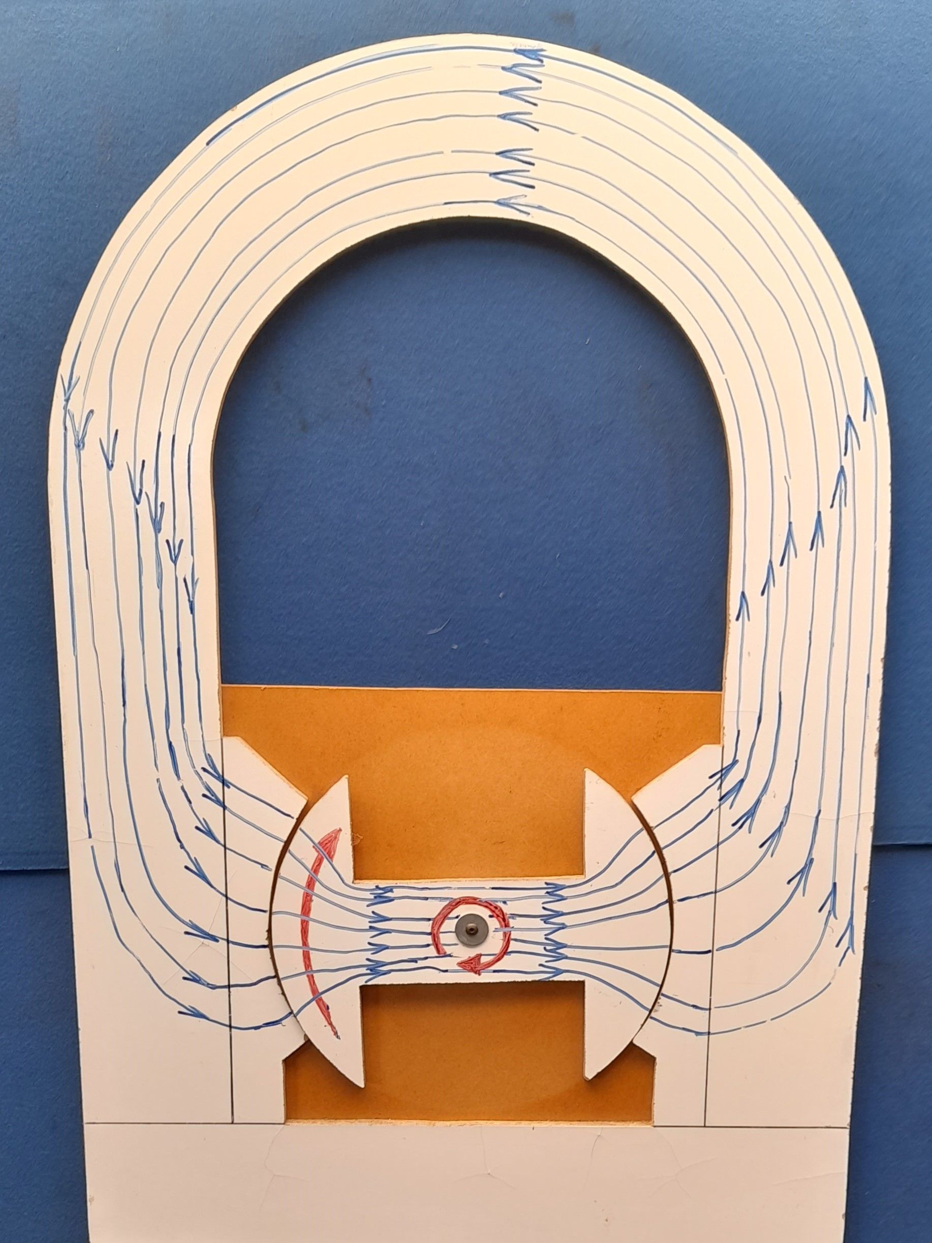
1: This picture shows the basic layout of the component parts of the magneto as just described. Note everything is mounted on a base plate. This needs to be non-magnetic (brass or aluminium) so that there is no path for the lines of magnetic flux - they are all concentrated through the magnet, pole pieces and laminated core - the coil windings are omitted for clarity.
As can be seen, the lines of magnetic flux flow through the laminated core. The armature is free to run on bearings so the magnetic pull on the laminated core results in the core coming to rest in the position shown. In this position, the armature acts as a 'keeper' to ensure that the magnet keeps it's magnetic strength.
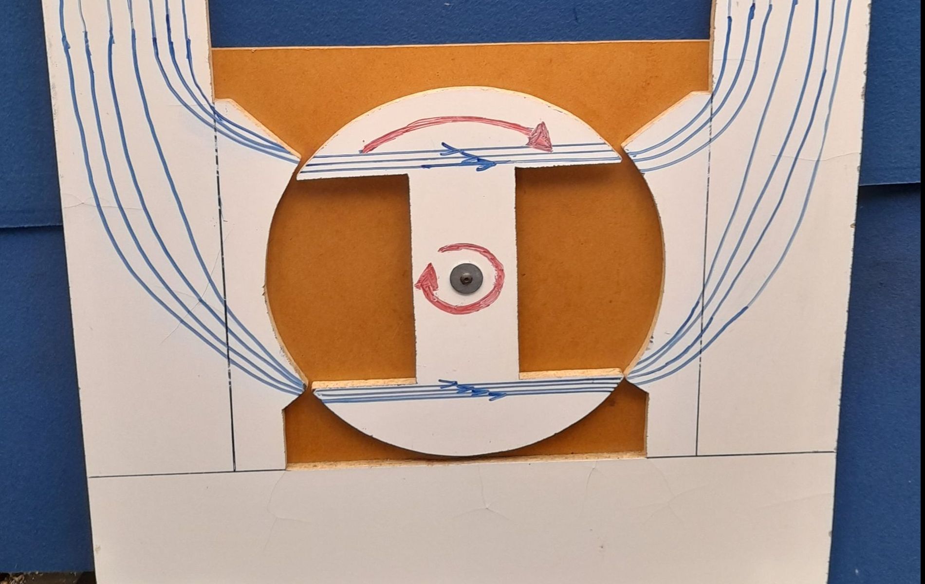
When it's time to start the engine, the crank will be turned by some means (pull cord, kickstart, crank handle, electric starter, bump/push start or whatever). The magneto is driven by the crank so the armature will turn - clockwise in our example.
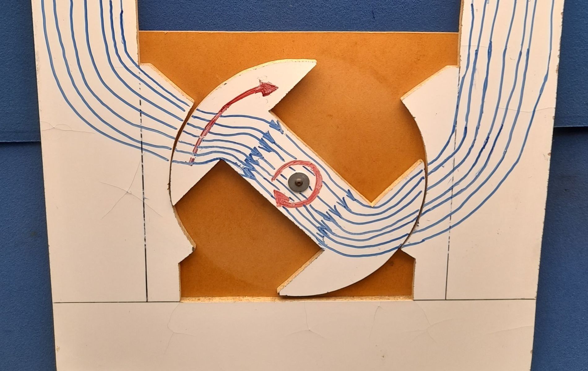
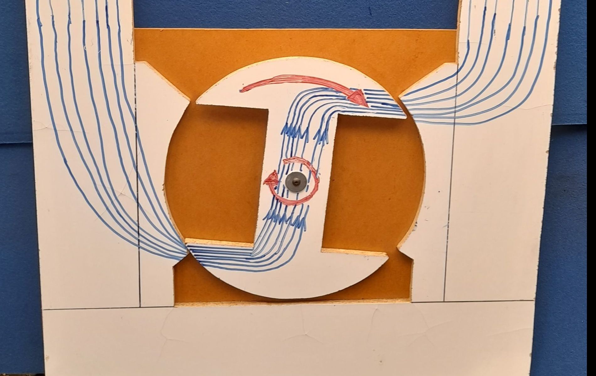
3: Further rotation results in further increases in flux density and magnetic field strength. When the armature is being turned by hand, it will be noticed that the armature starts to show a reluctance to turn. This is caused by the magnet trying to 'hang' on to the armature core - the magnet is RESISTING the armature's turn.
Before moving on, take note of the direction of the lines of flux through the armature core. They are flowing AWAY from the red rotation arrow.
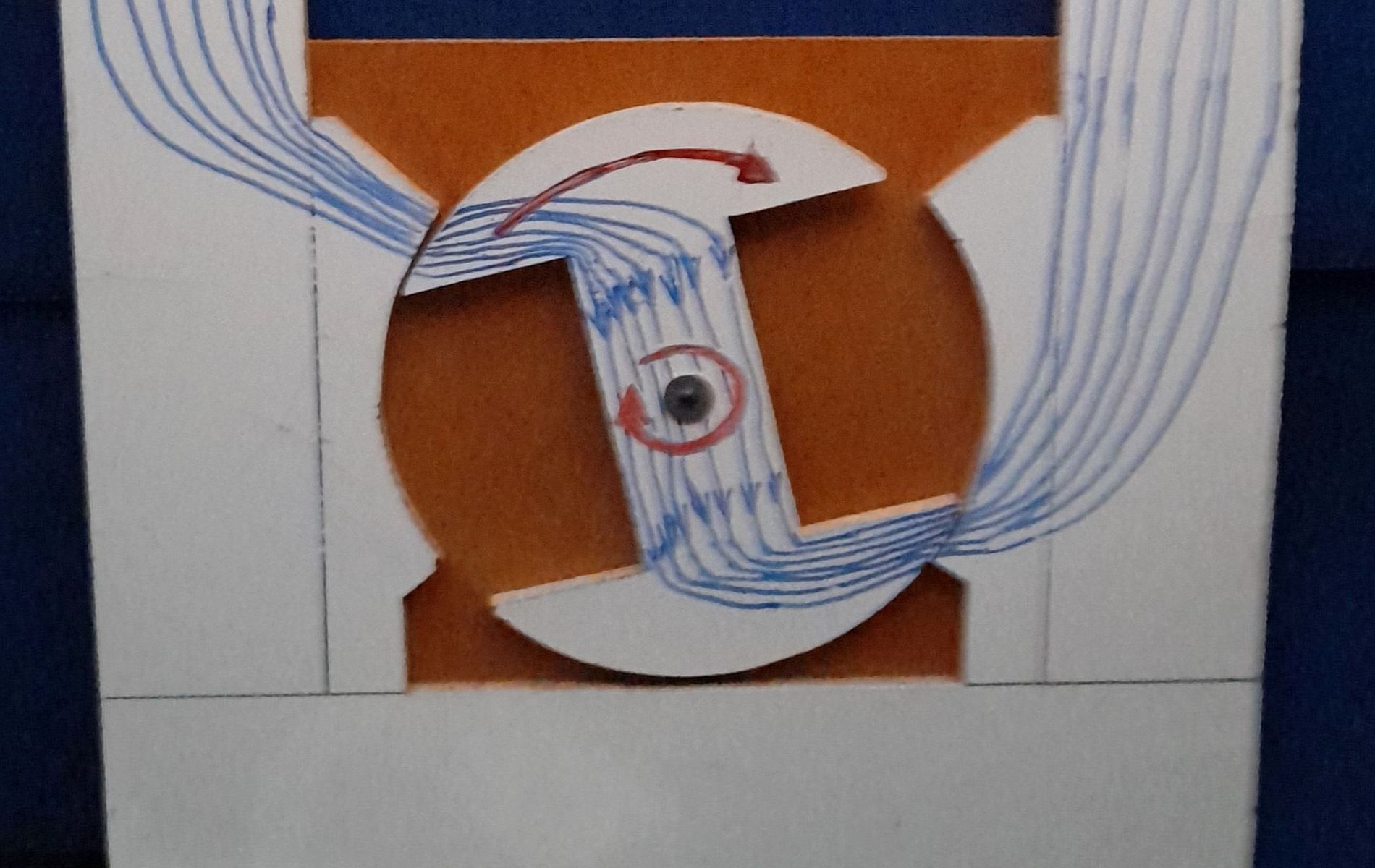
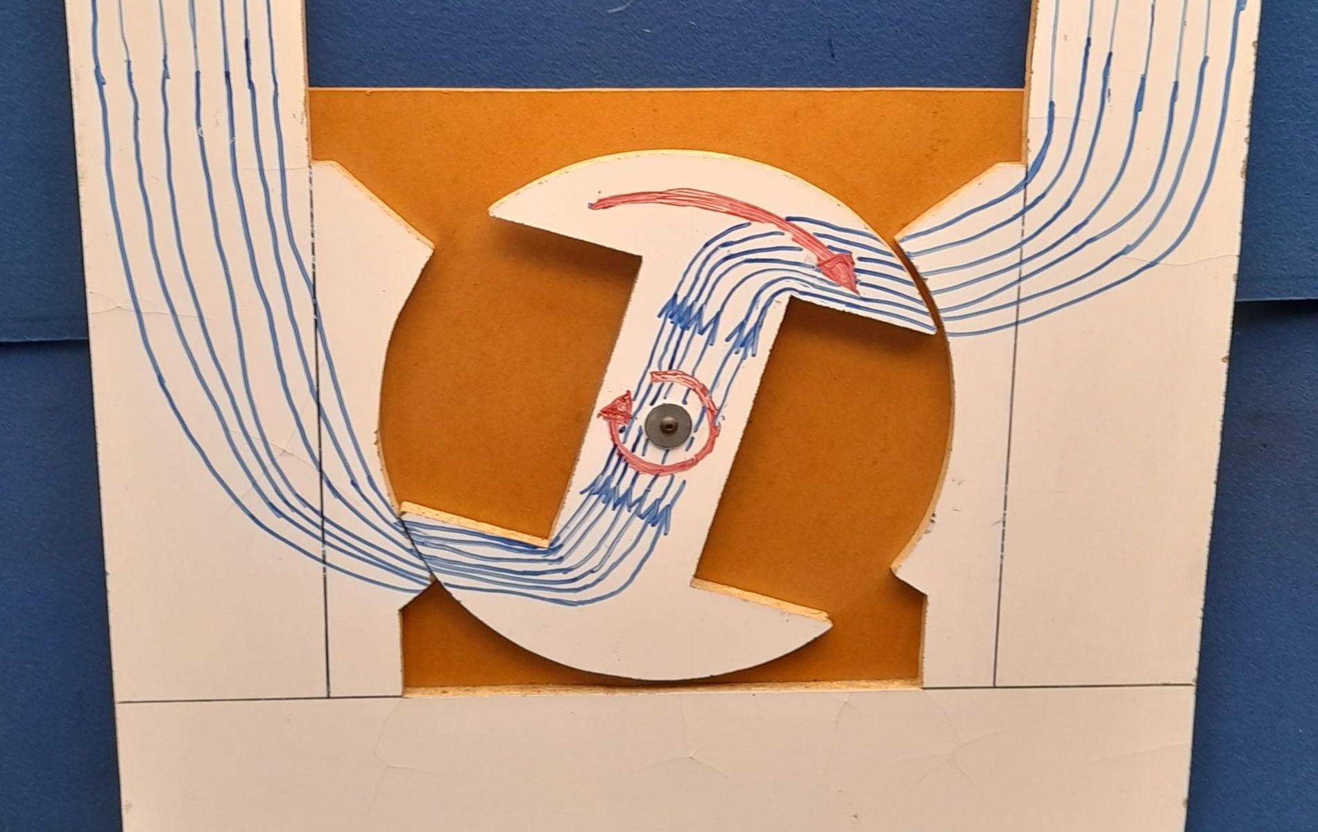
4: Only a few degrees more rotation and the lines of flux now pass straight across the armature core from side to side.
Note that there are NO lines of flux passing through the centre of the armature core.
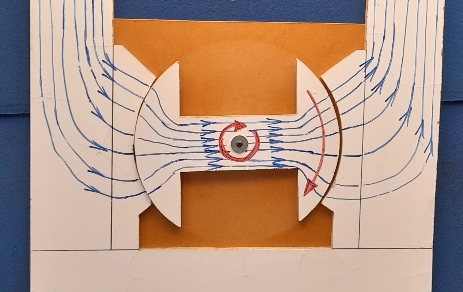
5: A few more degrees and the lines of flux start to flow through the centre of the armature again. The magnet is now attempting to pull the armature round further - ASSISTING it's rotation.
Note that the lines of magnetic flux are now flowing TOWARDS the red direction arrow.
6: A few degrees of rotation more and the lines of flux have started to spread out, the density of the lines has decreased and the magnetic field strength has reduced.
7: Here, the armature core has continued to rotate until it is a position similar to that in picture 1. The difference is that the armature has rotated 180° (the red direction arrow is now on the right) and the lines of magnetic flux are now flowing in the armature core in the opposite direction - towards the red direction arrow.
If the armature core is rotated a further 180°, much the same sequence of events will be repeated. The only difference being that the reversal of the magnetic lines will be in the opposite direction.
In summary, each revolution of the armature will include two reversals of the magnetic lines of flux through the centre limb of the armature core.
The ends of the armature core are closed off with a pair of non-magnetic caps which each include a short shaft to make up a spindle so that the armature can be rotated. Brass is the most common material used for the end caps and in early magnetos, the drive end spindle was also brass. The need for a stronger drive end spindle introduced the steel spindle in the centre of the brass end cap. This bi-metal end cap/spindle became almost universal though some manufacturers used a one piece stainless steel (non-magnetic) drive end for some magneto models. The use of non-magnetic materials for the end caps ensured that the lines of magnetic flux could not pass through them - they had to pass through the centre limb of the armature core as described above. The primary and secondary coils are wound round the centre limb of the iron core so that means that the lines of magnetic flux also pass through the centre of both coils. With the drive spindle at one end, the end cap at the opposite end carries a switch known as the contact breaker (CB) points.
The start of the primary coil winding is connected to the metal body of the armature and the other end to one of the contacts on the CB points. The other contact of the CB points is connected to the metal body of the armature so that the CB points and the primary coil are in parallel. This arrangement produces a closed electrical circuit when the CB points are closed. If the CB points are closed, when the armature (and therefore coil) is rotated within the magnet's magnetic field, a current is induced in the coil. The direction of that induced current flow will depend on the direction of the winding of the coil and the direction of flow of the magnetic lines of flux. The direction of the winding is fixed of course but the direction of the lines of flux reverses twice per revolution as described above. As a result the direction of induced current in the primary coil also reverses twice per revolution.
When current flows in a conductor, a separate magnetic field is created around that conductor. By winding the conductor in the shape of a coil, the strength of that coil winding's magnetic field is greatly intensified. By winding that coil on a laminated iron core, the magnetic field is concentrated within that core.
All the time the CB points are closed and the coil is rotating in the magnet's magnetic field, a current will flow in the primary coil winding. That means the armature core in a magneto is carrying two sets of lines of flux, one due to the permanent magnet and one due to the induced current flowing in the primary coil winding.
New Paragraph